Electron beam irradiation apparatus, electron beam irradiation method, and apparatus for and method of manufacturing disc-shaped object

a technology of electron beam irradiation and disc-shaped object, which is applied in the direction of material analysis using wave/particle radiation, instruments, nuclear engineering, etc., can solve the problems of increasing equipment cost, increasing weight and size of apparatus, and inability to form protective layers of sufficient quality, etc., and achieves the effect of reducing the rotation speed of disc-shaped objects

Inactive Publication Date: 2006-06-15
TDK CORPARATION
View PDF0 Cites 14 Cited by
  • Summary
  • Abstract
  • Description
  • Claims
  • Application Information

AI Technical Summary

Benefits of technology

[0010] It is an object of the present invention to provide an electron beam irradiation apparatus and an electron beam irradiation method that are capable of easily curing a material that is hard to be cured by irradiation of ultraviolet rays and of reducing the number of electron beam irradiation tubes to be used.
[0011] It is another object of the present invention to provide an apparatus for and a method of manufacturing a disc-shaped object that are capable of forming a layer having functionability on the disc-shaped object efficiently and at a low cost by use of a material that is hard to be cured by the irradiation of the ultraviolet rays.

Problems solved by technology

When especially the protection layer, etc. is formed of a material such as silicon compound, fluorine compound, etc. that exhibit radial polymerization double-bond, however, there might be a case in which a characteristic as the protection layer, etc. deteriorates unless a reaction initiator is added thereto in such a case, and the protection layer is hard to be cured by the irradiation of the ultraviolet rays, with the result that the protection layer having a sufficient quality can not be formed (refer to Japanese Patent Laid-Open Application Publication No. 4-019839, Japanese Patent Laid-Open Application Publication No. 11-162015, Japanese Patent Laid-Open Application Publication No. 7-292470, Japanese Patent Laid-Open Application Publication No. 2000-64042).
If the electron beam irradiation apparatus involves using the plurality of electron beam irradiation tubes, the apparatus increases both in weight and in size, an equipment cost rises because of the electron beam irradiation tube being comparatively expensive, and a running cost increases with a rise in amounts of consumption of an N2 gas for cooling and of electric power.
A manufacturing cost increases due to these factors.

Method used


Image

  • Electron beam irradiation apparatus, electron beam irradiation method, and apparatus for and method of manufacturing disc-shaped object
  • Electron beam irradiation apparatus, electron beam irradiation method, and apparatus for and method of manufacturing disc-shaped object
  • Electron beam irradiation apparatus, electron beam irradiation method, and apparatus for and method of manufacturing disc-shaped object

Examples


first embodiment

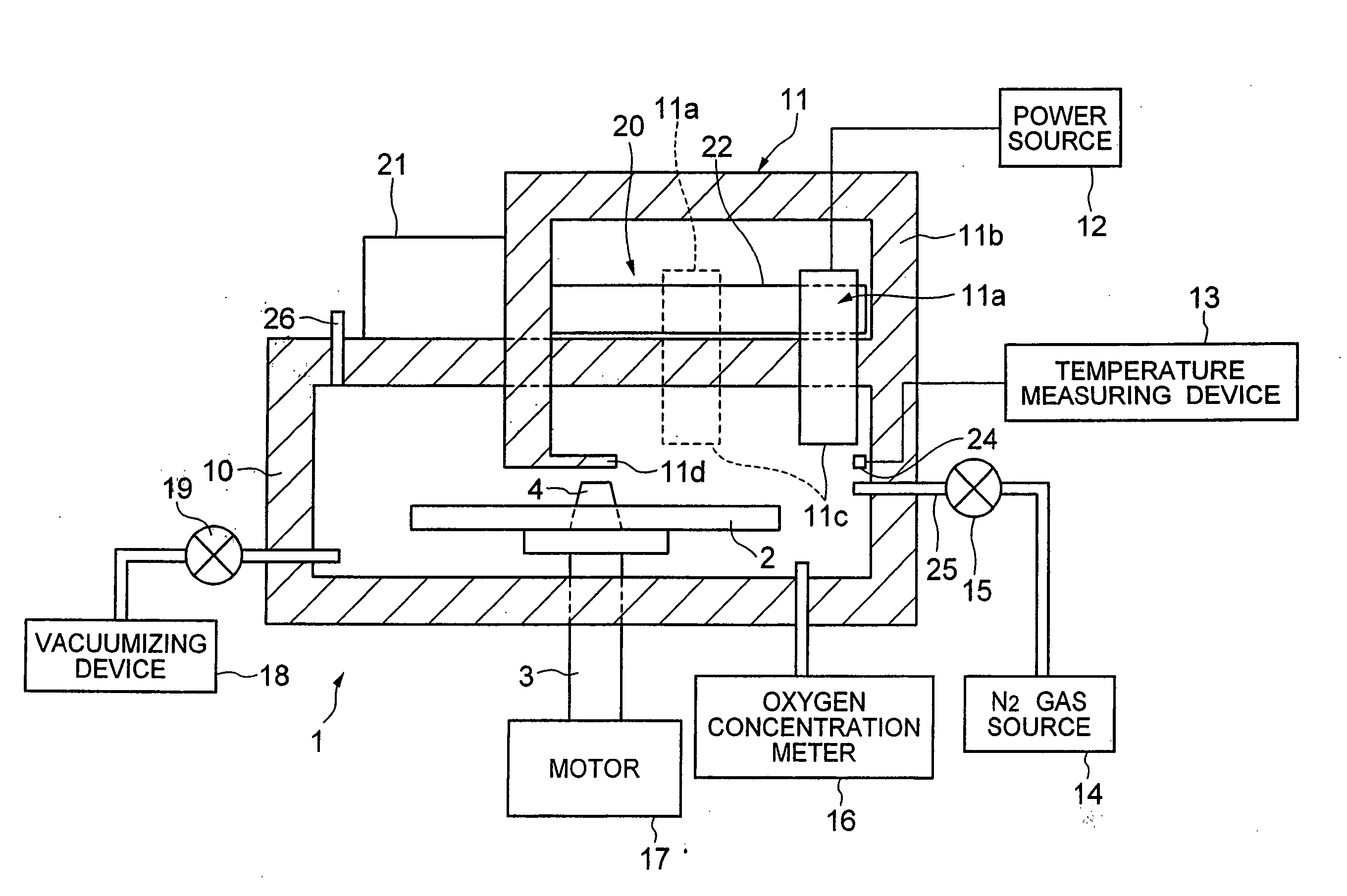
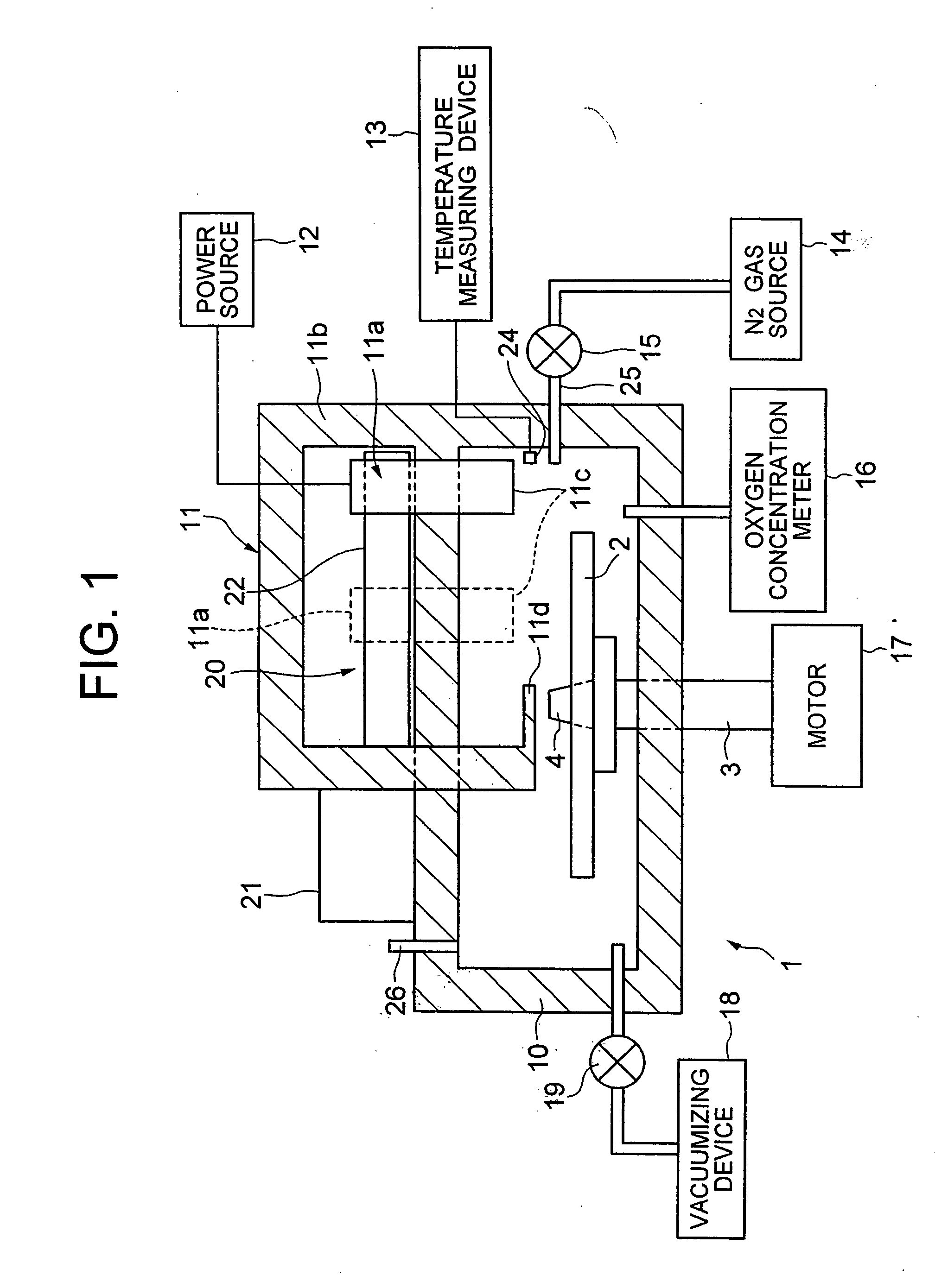
[0050] The electron beam irradiation apparatus in the first embodiment is constructed to irradiate a disc-shaped irradiation target object with electron beams while moving a single electron beam irradiation tube.

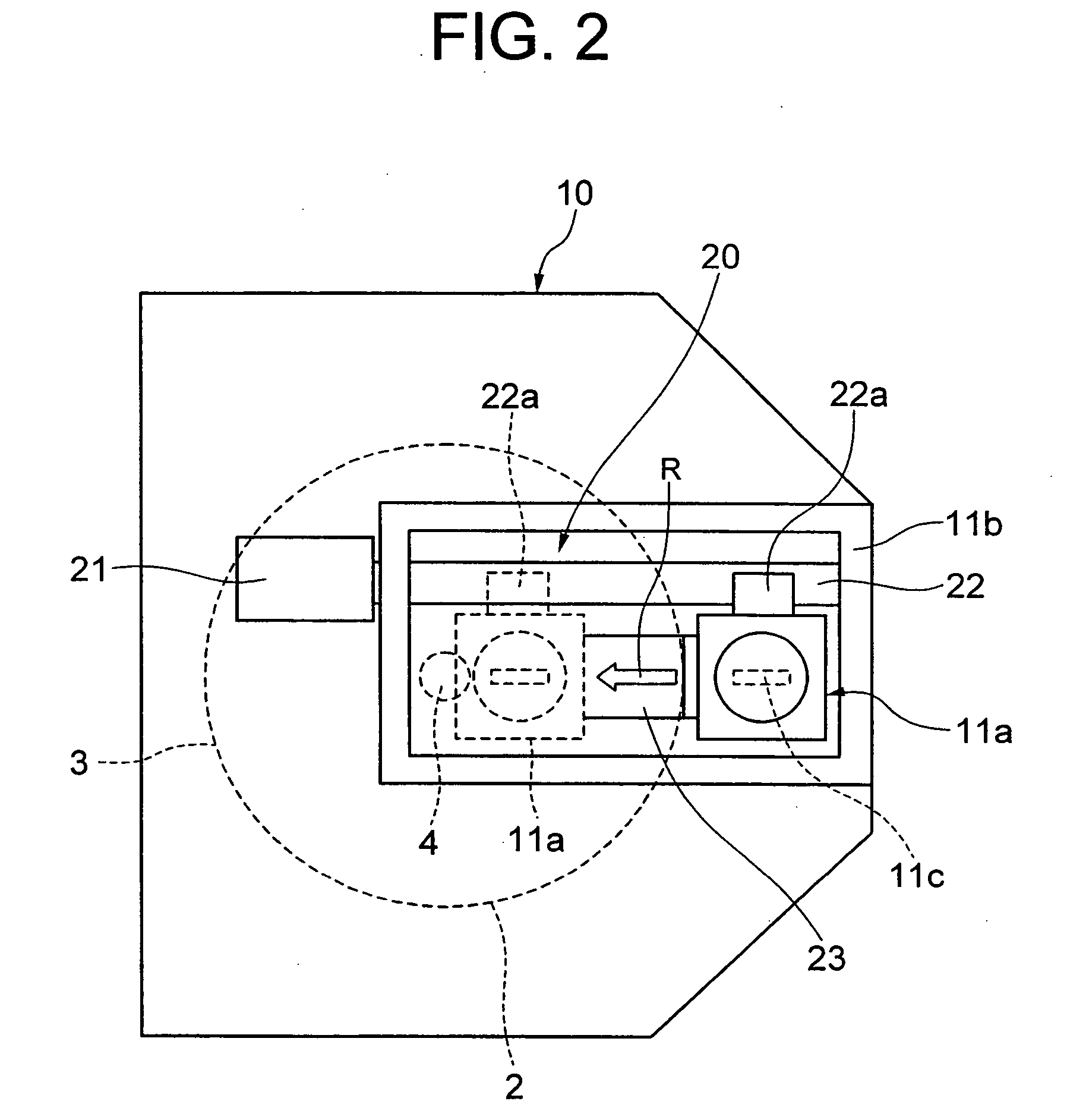
[0051]FIG. 1 is a side view schematically showing the electron beam irradiation apparatus in the first embodiment. FIG. 2 is a plan view of the principal portions of the electron beam irradiation apparatus in FIG. 1. FIG. 3 is a block diagram showing a control system of the electron beam irradiation apparatus in FIG. 1. FIG. 4 is a flowchart showing an operation of the electron beam irradiation apparatus in FIGS. 1 through 3. FIG. 5 is a graph schematically showing a relation between a radius-directional position of an electron beam irradiation tube 11a and a moving velocity of the electron beam irradiation tube 11a of the electron beam irradiation apparatus in FIGS. 1 through 3. FIG. 17 is a plan view showing a positional relation in plane between the on-rotating disc-shape...

third embodiment

[0109]FIG. 14 is a side view showing the same processes, as those in FIG. 6, of the manufacturing apparatus, for forming the lubricating layer, etc. on the disc-shaped medium in the FIG. 15 is a plan view of principal portions of the manufacturing apparatus in FIG. 14. FIG. 16 is a diagram schematically showing a relation between a radius-directional position of the electron beam irradiation tube 11a in FIGS. 11 and 15 with respect to the disc-shaped medium and a rotating speed of the disc-shaped medium.

[0110] As shown in FIG. 14, in the manufacturing apparatus according to the third embodiment, the electron beam irradiation unit 11 includes the electron beam irradiation tube 11a fixedly disposed in an upper position in the vicinity of the center of the disc-shaped medium 49 within the irradiation tube container 11b.

[0111] Further, the rotational tray unit 52a and the rotational tray unit 10b are independently rotationally controlled in order to exchange the rotational tray units ...


PUM

PropertyMeasurementUnit
oscillation wavelengthaaaaaaaaaa
acceleration voltageaaaaaaaaaa

Abstract

Disclosed are an electron beam irradiation apparatus and an electron beam irradiation method that are capable of easily curing a material that is hard to be cured by irradiation of ultraviolet rays and of reducing the number of electron beam irradiation tubes. The electron beam irradiation apparatus has a motor for rotationally driving an irradiation target object, a shield container for rotatably accommodating the irradiation target object, and an electron beam irradiation unit provided in the shield container so that the surface of the irradiation target object is irradiated with electron beams, wherein the electron beam irradiation unit and the irradiation target object are relatively moved when the electron beam irradiation unit irradiates the surface of the irradiation target object with the electron beams during a rotation of the irradiation target object.

Description

INCORPORATION BY REFERENCE [0001] The present application claims priority under 35 U.S.C. §119 to Japanese Patent Application No. 2004-019681 filed on Jan. 28, 2004. The content of the application is incorporated herein by reference in its entirety. BACKGROUND OF THE INVENTION [0002] 1. Field of the Invention [0003] The present invention relates to an electron beam irradiation apparatus and electron beam irradiation method for irradiating electron beams and to an apparatus for and a method of manufacturing a disc-shaped object. [0004] 2. Description of the Prior Art [0005] Optical discs such as a CD (Compact Disc), a DVD (Digital versatile Disc), and the like have hitherto been utilized as optical information recording mediums. Over the recent years, however, there has been a progress of developing a blue semiconductor laser of which an oscillation wavelength is on the order of 400 nm. The development of a next generation high-density optical disc such as a high-density DVD, and the...

Claims


Application Information

Patent Timeline
Patent Type & Authority Applications(United States)
IPC IPC(8): G21K5/10A61N5/10G01N23/00G11B7/26G21K5/00G21K5/04
CPCH01J37/3023H01J37/3056H01J2237/20214H01J2237/20221H01J2237/30461H01J2237/3156H01J2237/316H01J2237/3165
Inventor YONEYAMA, KENJITANAKA, KAZUSHIUSAMI, MAMORU
Owner TDK CORPARATION
Why Eureka
Try Eureka