System and method for providing power control of an energy storage system

Inactive Publication Date: 2006-06-15
GENERAL ELECTRIC CO
View PDF23 Cites 44 Cited by
  • Summary
  • Abstract
  • Description
  • Claims
  • Application Information

AI Technical Summary

Benefits of technology

[0006] In accordance with one aspect of the present technique a power control system for an energy storage system is disclosed. The power control system includes a control unit comprising: a circuit adapted to determine a state of charge of an energy storage unit in a high side power source and to provide

Problems solved by technology

However, the transient response of such systems is reduced when a sudden high power veh

Method used


Image

  • System and method for providing power control of an energy storage system
  • System and method for providing power control of an energy storage system
  • System and method for providing power control of an energy storage system

Examples


Embodiment Construction

[0019] In the subsequent paragraphs, for a better understanding of the various aspects of the present techniques, the different circuits, systems, and methods for implementation of the different aspects for the method for providing power control to the energy storage system will be described in greater detail. The various aspects of the present techniques will be explained, by way of example only, with the aid of figures hereinafter.

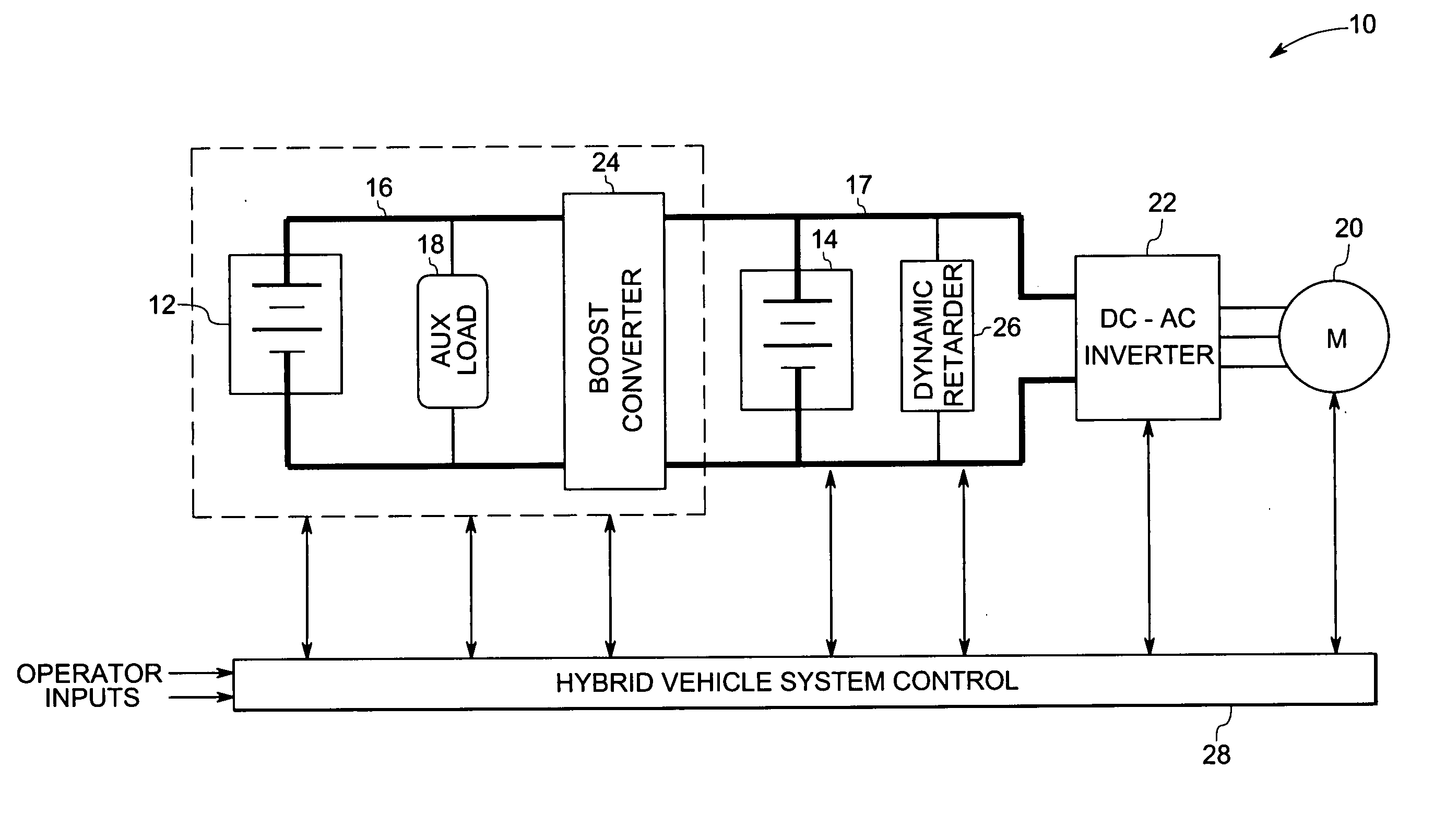
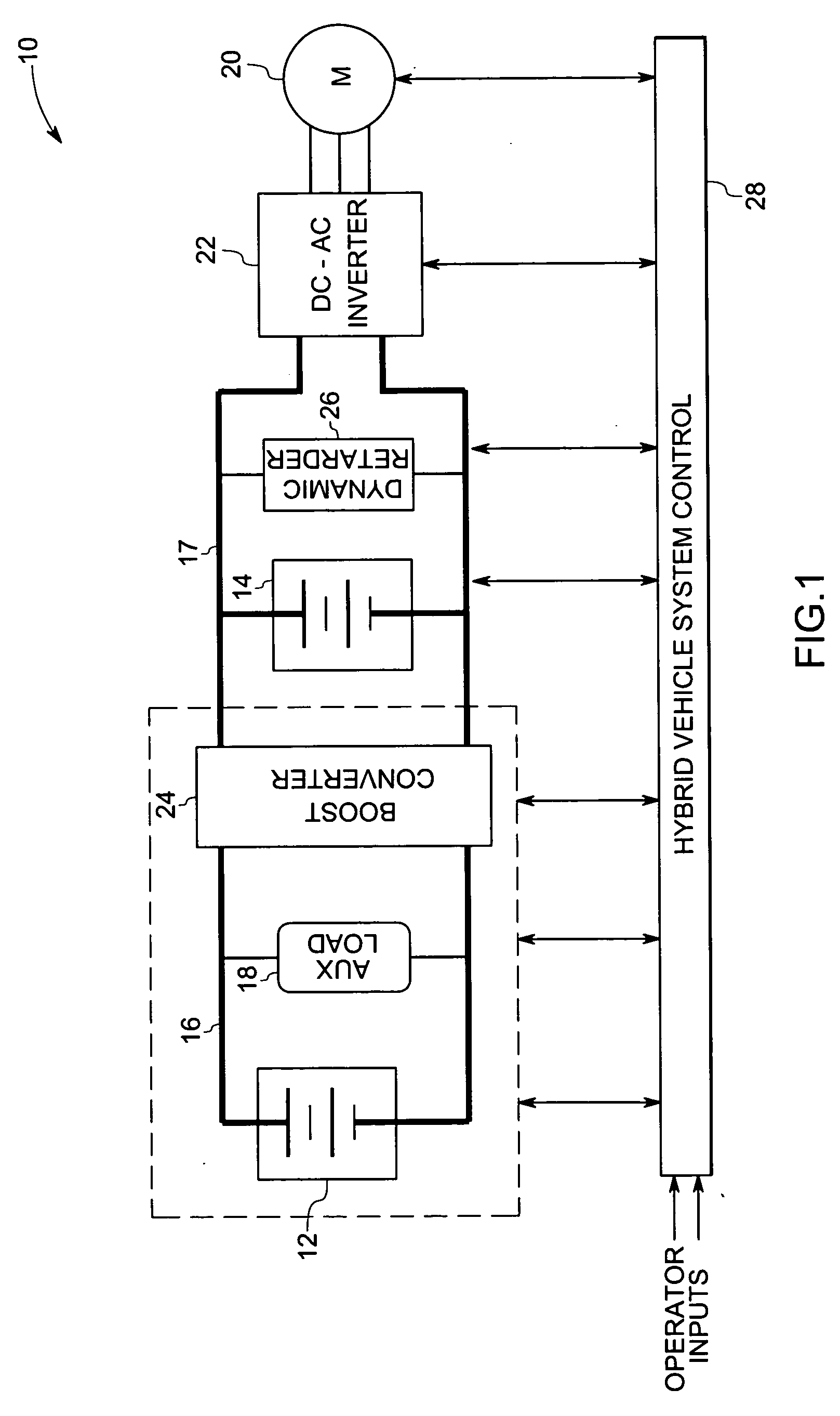
[0020] Turning now to the drawings, FIG. 1 is a schematic diagram of an exemplary hybrid vehicle system 10 having a low side power source 12 and a high side power source 14, in accordance with certain aspects of the present technique. The high side power source 14 may additionally be referred to as a traction battery 14 herein. The low side power source is coupled to a traction drive system (not shown) by a direct current (DC) link 16. The low side power source 12 may be used to supply power to one or more auxiliary loads 18. The low side power source 1...


PUM


Abstract

A control circuit comprises a circuit adapted to determine a state of charge of a high side power source using a sensed output current to provide a variable gain signal based on the state of charge. The control circuit may also contain a circuit configured to provide a fixed gain signal based on the current of the high side power source and a circuit configured to combine the variable gain signal and the fixed gain signal to create a power command.

Description

BACKGROUND [0001] The invention relates in general to hybrid vehicle systems, and in particular to power control of energy storage in hybrid electric drives and vehicle systems. Hybrid systems are advantageous due to their ability to increase the fuel efficiency of the vehicle system and to reduce air pollution. [0002] Typically, hybrid vehicle systems include a low side power source and a high side power source. The low side power source and the high side power source operate in conjunction to supply power to a device such as a motor, which may be used, for example, to propel a hybrid vehicle. The low side power source, which typically has a high energy density, may comprise a battery, a heat engine, an ultracapacitor, a flywheel or the like. The heat engine may include any engine that burns a fuel to produce mechanical work, such as an internal combustion engine, a turbine engine, a diesel engine or the like. [0003] Some vehicles use electric traction motors as a component of the ...

Claims


Application Information

Patent Timeline
IPC IPC(8): B60L1/00B60L50/30
CPCB60L7/06Y02T10/70B60L7/22B60L11/005B60L11/14B60L11/16B60L11/1803B60L11/1868B60L11/1887Y02T10/7022Y02T10/7033Y02T10/7066Y02T10/7077Y02T90/34B60L2200/26Y02T10/7027B60L7/14B60L50/16B60L50/30B60L50/40B60L50/51B60L58/20B60L58/40Y02T10/7072Y02T90/40
Inventor KING, ROBERT DEANSONG, DONGWOOSALASOO, LEMBIT
Owner GENERAL ELECTRIC CO
Why Eureka
Try Eureka