Radio frequency amplitude keying demodulation circuit with large input dynamic range

A technology of amplitude keying and demodulation circuit, which is applied in short-distance wireless communication occasions where uncertain factors affect its modulation degree, and the scheme is realized: [0008] In the field of large input dynamic range, it can achieve signal accuracy, improve signal-to-noise ratio, Improve the effect of the response

Inactive Publication Date: 2012-07-04
JIAXING LIANXING MICROELECTRONICS
View PDF4 Cites 18 Cited by
  • Summary
  • Abstract
  • Description
  • Claims
  • Application Information

AI Technical Summary

Problems solved by technology

There are many disadvantages in the prior art amplitude keying demodulation: First, because its receiving sensitivity is mainly determined by the gain of its front-end amplifier circuit, and the relationship between the gain and sensitivity of its front-end amplifier circuit presents an exponential relationship, it is necessary to greatly improve the sensitivity. Greatly increase the gain of its front-end amplifier circuit, but due to power consumption, noise, etc., the gain of its front-end amplifier circuit cannot be too large, so this limits the detection of high-sensitivity input signals by the existing circuit structure
Second, the traditional design requires additional filter capacitors and inductors, which not only increases the difficulty of system design, but also increases the complexity of the peripheral circuits of the chip
Third, in the traditional design, because the comparison voltage of the comparison circuit adopts a fixed level, the traditional design cannot be applied to systems with different modulation degrees. The existing technology generally first determines the modulation degree, and then changes the chip The external control signal changes the comparison level of the comparison circuit, but in practical applications, the signal may affect its modulation degree due to uncertain factors such as noise, which affects the output bit error rate of the traditional design

Method used


Image

  • Radio frequency amplitude keying demodulation circuit with large input dynamic range
  • Radio frequency amplitude keying demodulation circuit with large input dynamic range
  • Radio frequency amplitude keying demodulation circuit with large input dynamic range

Examples


no. 1 example

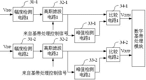
[0076] Figure 3a A block diagram of the two-way differential configuration of the amplitude keying demodulation circuit in the first embodiment of the present invention is given. The two-way amplitude keying demodulation circuit composed of two-way differential is completely the same. The amplitude values ​​of the input signals VINP and VINN are detected by the amplitude detection circuits 31-1 and 31-2 respectively, and the detected amplitude values ​​are passed through Gaussian filters 32-1 and 32-2 based on the Butterworth filter respectively. , to filter out the interference of high-frequency signals, the Gaussian filters 32-1 and 32-2 are controlled by the baseband processing control signal to control their bandwidth, and configure the required bandwidth to meet the requirements of different rates and different communication systems. The outputs of the Gaussian filters 32-1 and 32-2 are provided to the peak detection circuits 33-1 and 33-2, each obtaining a peak hold si...

no. 2 example

[0081] Figure 6A specific circuit configuration block diagram from the Gaussian filter circuit to the output of the comparison circuit of the amplitude keying demodulation circuit of the embodiment of the present invention is given, including a Gaussian filter circuit 61 , a peak detection circuit 62 and a comparison circuit 63 . The Gaussian filter circuit 61 is composed of variable resistors R1, R2, variable capacitors C1, C2 and an operational amplifier circuit 601, which is a typical low-pass filter, using a second-order Butterworth filter structure,  … . The Gaussian filter circuit changes the cut-off frequency by adjusting the values ​​of resistors R1 and R2 and capacitors C1 and C2 in the circuit, and suppresses the high-frequency components in the input by filtering the output signal of the amplitude detection circuit through the Gaussian filter circuit. VIN is the output signal of the amplitude detection circuit, which is output by the Gaussian filter circuit 61. The...


PUM


Abstract

The invention discloses a radio frequency amplitude keying demodulation circuit with large input dynamic range, which comprises an amplitude detection circuit, a Gaussian filter circuit, a peak detection circuit and two branches of difference amplitude keying demodulation circuits of a comparison circuit. The amplitude detection circuit is formed by a fixed gain amplifier with S poles in series connection and an amplitude detection and conversion circuit. Each branch of the amplitude keying demodulation circuits includes that input signals are amplified to i fuzzy amplitude keying signals through the amplitude detection circuit, the i fuzzy amplitude keying signals are added and converted into high-low voltage amplitude signals, high frequency components are filtered through the Gaussian filter circuit, the filtered signals pass through the peak detection circuit to obtain high-low average amplitude signals, and the average amplitude signals and the signals filtered by the Gaussian filter circuit are compared through the comparison circuit to obtain demodulation signals output by the radio frequency amplitude keying demodulation circuit. The radio frequency amplitude keying demodulation circuit with the large input dynamic range can be flexibly used for demodulating amplitude detection signals with modulation degree ranging from 0.5 to 0.9, thereby being capable of being applied to the front end of a radio frequency receiver with input signals reaching up to 60dB dynamic range.

Description

Background technique [0001] In recent years, with the wide application of intermittent low-speed products, such as home security, garage door management and remote control, short-distance wireless communication technology has been widely used, and the amplitude keying modulation method used in short-distance wireless communication technology has become more and more popular . Because the amplitude keying modulation method has simple modulation, simple system design, low system power consumption, and bit error rate increases with the increase of signal propagation distance, it is especially suitable for short-distance wireless communication occasions. [0002] As we all know, different systems have different depths of amplitude keying modulation. Obviously, a demodulator that can only be applied to one modulation method can only meet a specific system requirement, and cannot adapt to the specific needs of different systems. At the same time, the traditional The sensitivity of ...

Claims


Application Information

Patent Timeline
Patent Type & Authority Applications(China)
IPC IPC(8): H04B1/40H04L27/06H03D1/18H04B1/44
Inventor 何晓丰莫太山钱敏马成炎
Owner JIAXING LIANXING MICROELECTRONICS
Why Eureka
Try Eureka