Eureka AIR delivers breakthrough ideas for toughest innovation challenges, trusted by R&D personnel around the world.

Program conversion device, program conversion and execution device, program conversion method, and program conversion and execution method

a technology of program conversion and execution device, applied in the direction of instruments, computing, electric digital data processing, etc., can solve the problems of increasing the overall execution time, increasing and affecting so as to enhance the execution performance of the part, the effect of reducing the complexity of the compensation code and reducing the overall execution tim

Inactive Publication Date: 2006-06-15
PANASONIC CORP
View PDF6 Cites 35 Cited by
  • Summary
  • Abstract
  • Description
  • Claims
  • Application Information

AI Technical Summary

Benefits of technology

[0015] The term “corresponding to” used here means code has substantially same contents as instructions in the source program. It should be noted however that registers to be accessed change depending on a memory type of the computer. Also, an execution path means a sequence of instructions which are consecutively executed. When a program branches at a conditional branch, an execution path corresponds to a single one of a plurality of branch targets of that conditional branch. The object program generated by the object program generating unit may be intermediate code or an executable program that is ready to run on the computer. The intermediate code means code that is generated during a process of converting the source program into the executable program so as to ease handling of code by the program conversion de vice, and has the contents corresponds to the source program.
[0056] Here, the object program generating step may generate the object program which causes the computer to retain any of the stopped sets of second code without deleting.

Problems solved by technology

If a program includes more complex conditional branches, compensation code becomes more complex.
In some cases, when control takes an execution path including compensation code, the program may run slower than expected.
Thus, the provision of compensation code can result in an increase in overall execution time.

Method used


Image

  • Program conversion device, program conversion and execution device, program conversion method, and program conversion and execution method
  • Program conversion device, program conversion and execution device, program conversion method, and program conversion and execution method
  • Program conversion device, program conversion and execution device, program conversion method, and program conversion and execution method

Examples


first embodiment

[0098] A compiler device of a first embodiment of the present invention generates an executable program for a computer of a memory sharing type.

(Overview)

[0099] First, an overview of the present invention is given below, by referring to FIGS. 2 and 3.

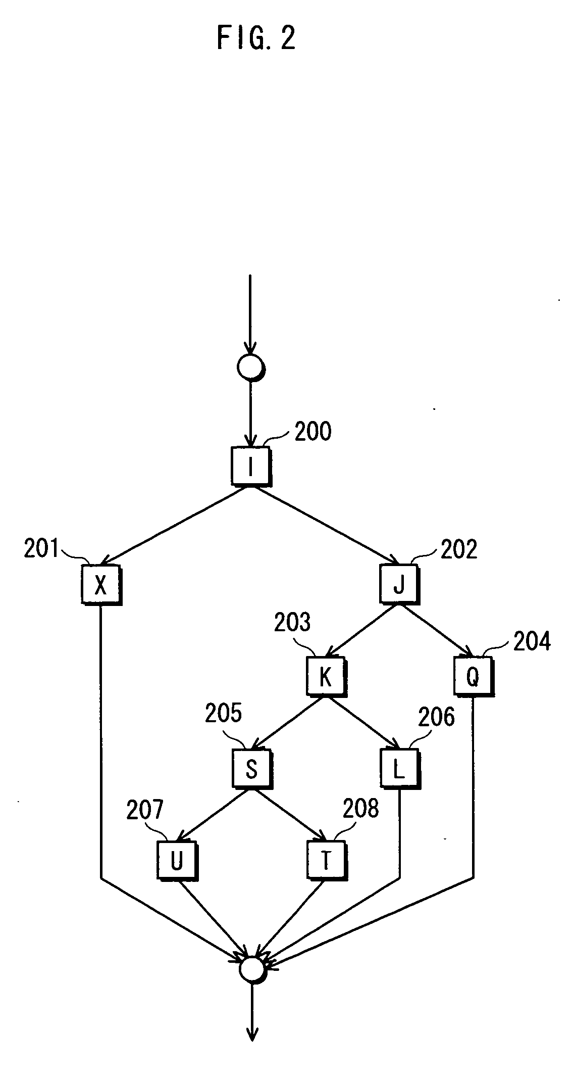
[0100] Suppose the compiler device converts a source program one part of which has branches as shown in a control flow graph of FIG. 2, into an executable program.

[0101] In the drawing, blocks I 200, J 202, K 203, L 206, Q 204, S 205, T 208, U 207, and X 201 are each a basic block. As mentioned earlier, a basic block is a sequence of instructions containing no branch in a middle, though it may contain a branch at an end. The executable program generated by the compiler device is designed for use in a computer capable of executing two or more instructions in parallel.

[0102] The control flow graph of FIG. 2 includes five execution paths, namely, execution path I 200→J 202→Q 204, execution path I 200 J→202→K 203→S 205→T 208, executio...

second embodiment

[0202] A second embodiment of the present invention describes the case where the target hardware 130 is of the memory distribution type. The following explanation mainly focuses on the differences from the first embodiment.

[0203] The second embodiment differs from the first embodiment mainly in that, since each processor element is connected to a separate memory and uses a value in that memory, there is no danger of a performance drop caused by memory access contention, unlike in the case of the memory sharing type.

[0204] This is explained in detail using the code shown in FIGS. 12 to 14 and 21. FIG. 12 shows thread 1200 which has the same execution contents as thread 700 shown in FIG. 7. FIG. 13 shows thread 1300 which has the same execution contents as thread 800 shown in FIG. 8. FIG. 14 shows thread 1400 which has the same execution contents as thread 900 shown in FIG. 9. FIG. 21 shows main thread 2100 in the case of the memory distribution type.

[0205] When the target hardware...

third embodiment

[0212] The first and second embodiments describe the case where the number of instructions that can be execute in parallel by the target hardware 130 is known to the compiler device 100. However, there may be a case where the number of processor elements capable of parallel execution in the target hardware 130 is unknown. Such a case includes when the execution frequency information 140 and the memory information are provided to the compiler device 100 beforehand, and the compiler device 100 needs to generate the executable program 120 without transfer of information from the target hardware 130 to the compiler device 100. In such a case, code for obtaining the number of processor elements and code for setting the number of threads according to the number of processor elements need to be contained in the main thread. FIG. 11 shows code of main thread 1100 in the case where the number of processor elements is unknown. The following explains the execution contents of this code. Suppos...


PUM


Abstract

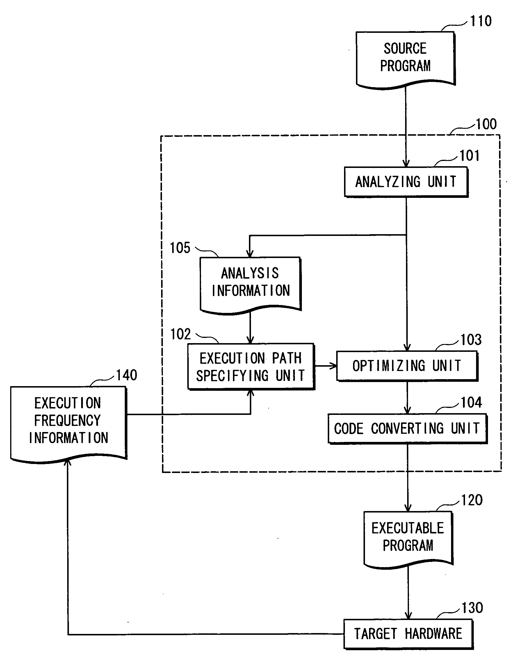
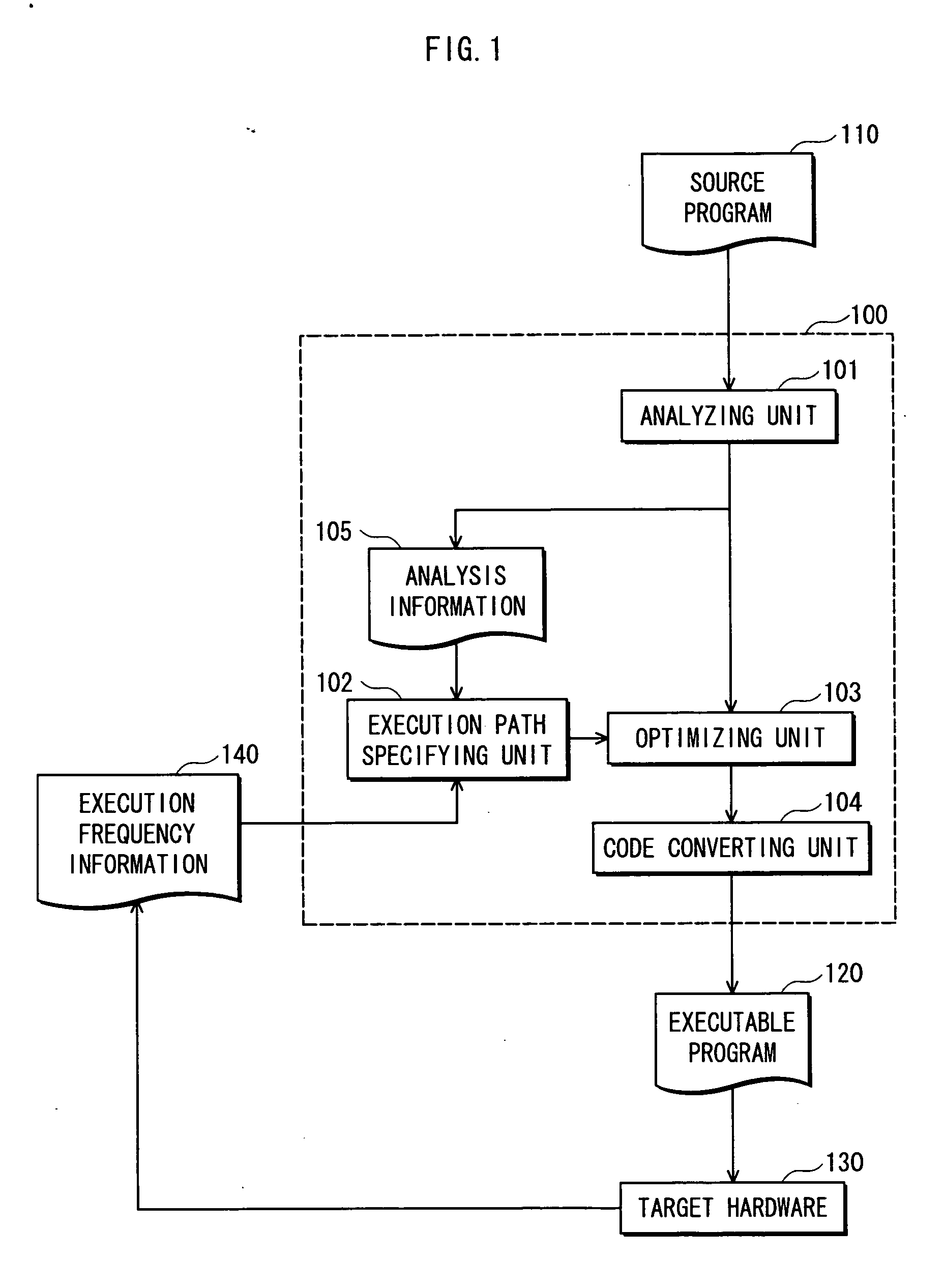
To provide a compiler device that generates an executable program for a computer capable of executing two or more instructions in parallel, without using compensation code in trace scheduling. The compiler device generates the executable program that causes the computer to concurrently execute code which is a substantially direct translation of the source program, and code generated by optimizing a sequence of instructions of a most frequent execution path in the source program.

Description

BACKGROUND OF THE INVENTION [0001] 1. Field of the Invention [0002] The present invention relates to optimization of a program by a compiler, and particularly relates to optimization based on an execution frequency of an execution path in a program. [0003] 2. Related Art [0004] Various efforts have been directed at developing compilers that convert a source program to an executable program which runs faster on target hardware. [0005] To increase an execution speed of an executable program, a compiler device performs instruction scheduling. Instruction scheduling includes global scheduling that reorders instructions in a program to enhance instruction-level parallelism, thereby achieving faster execution. Trace scheduling is one of such global scheduling methods. Here, a sequence of instructions in a program that include no conditional branch in a middle and are therefore consecutively executed, though it may contain a conditional branch at an end, is called a basic block. Convention...

Claims


Application Information

Patent Timeline
IPC IPC(8): G06F9/45
CPCG06F8/4441
Inventor HATANO, FUMIHIROTANAKA, AKIRA
Owner PANASONIC CORP
Why Eureka
Eureka Blog
Learn More