Matrix treatment of damaged sandstone formations using buffered HF-acidizing solutions

a technology of hf acidizing solution and matrix treatment, which is applied in the direction of fluid removal, chemistry apparatus and processes, and borehole/well accessories. it can solve the problems of limiting the productive (or injective) capacity of the well, affecting the process of dissolving siliceous minerals, and affecting the formation effect of the well

Inactive Publication Date: 2006-06-22
BAKER HUGHES INC
View PDF4 Cites 46 Cited by
  • Summary
  • Abstract
  • Description
  • Claims
  • Application Information

AI Technical Summary

Benefits of technology

[0034] In addition to its use in matrix acidizing, the invention is applicable in remediation of oil and gas and geothermal wells by the removal of unwanted deposits from the wellbore and production equipment. Such unwanted deposits form and/or accumulate in the wellbore, production and recovery equipment and well casing. Such accumulated deposits affect productivity and are typically removed prior to cementing or the introduction of completion fluids into the wellbore. Remediation treatment fluids are further typically used to remove such undesired deposits prior to the introduction of stimulation fluids. In a preferred embodiment, the invention is used to remove siliceous deposits inside well tubulars.
[0035] In well remediation applications, the acidizing so...

Problems solved by technology

In the course of drilling, or during production or workover, the vast majority of oil and gas wells are exposed to conditions that ultimately lead to formation damage.
Formation damage limits the productive (or injective) capacity of the well.
Unfortunately, the process of dissolving siliceous minerals is not simple.
The generation timing of such secondary and/or tertiary precipitates as well as their placement in critical locations, such as the near wellbore, ultimately may cause further formation damage and negate the benefit of the acid treatment.
This strategy dilutes the concentration of reaction products per unit volume of acid treating solution but, unfortunately, also reduces the total quantity of siliceous minerals that can be dissolved per unit volume of acid.
Such systems essentially limit the availability of hydrogen ions for generation of HF.
Unfortunately, the secondary and tertiary precipitat...

Method used


Image

  • Matrix treatment of damaged sandstone formations using buffered HF-acidizing solutions
  • Matrix treatment of damaged sandstone formations using buffered HF-acidizing solutions
  • Matrix treatment of damaged sandstone formations using buffered HF-acidizing solutions

Examples


example 1

[0040] About 100 ml of BJSSA and mud acid containing 12% HCl and 3% HF was placed into separate beakers. Then 2 grams of carbonate chips was added into the acids, under static conditions, at room temperature and at 180° F. and left to stand for 24 hours. The solubility of calcium carbonate in the HF-based acids is set forth in Table I:

TABLE IACIDSYSTEMSOBSERVATIONSBJSSANo effervescence or precipitation even after 24 hrs whenexamined at room temperature and at 180° F.Mud AcidStrong effervescence and formation of white precipitateafter initial 15 minutes at room temperature as well asat 180° F.

[0041] Table I illustrates the low reactivity of buffered HF-containing acidizing solution versus the rapid reaction of mud acid with calcium carbonate and the subsequent precipitation of calcium fluoride. The solubility of calcium carbonate is limited partly by the higher-than-normal pH of the buffered HF-acidizing solution (which reduces acid attack on the carbonate) and partly by the low so...

examples 2-5

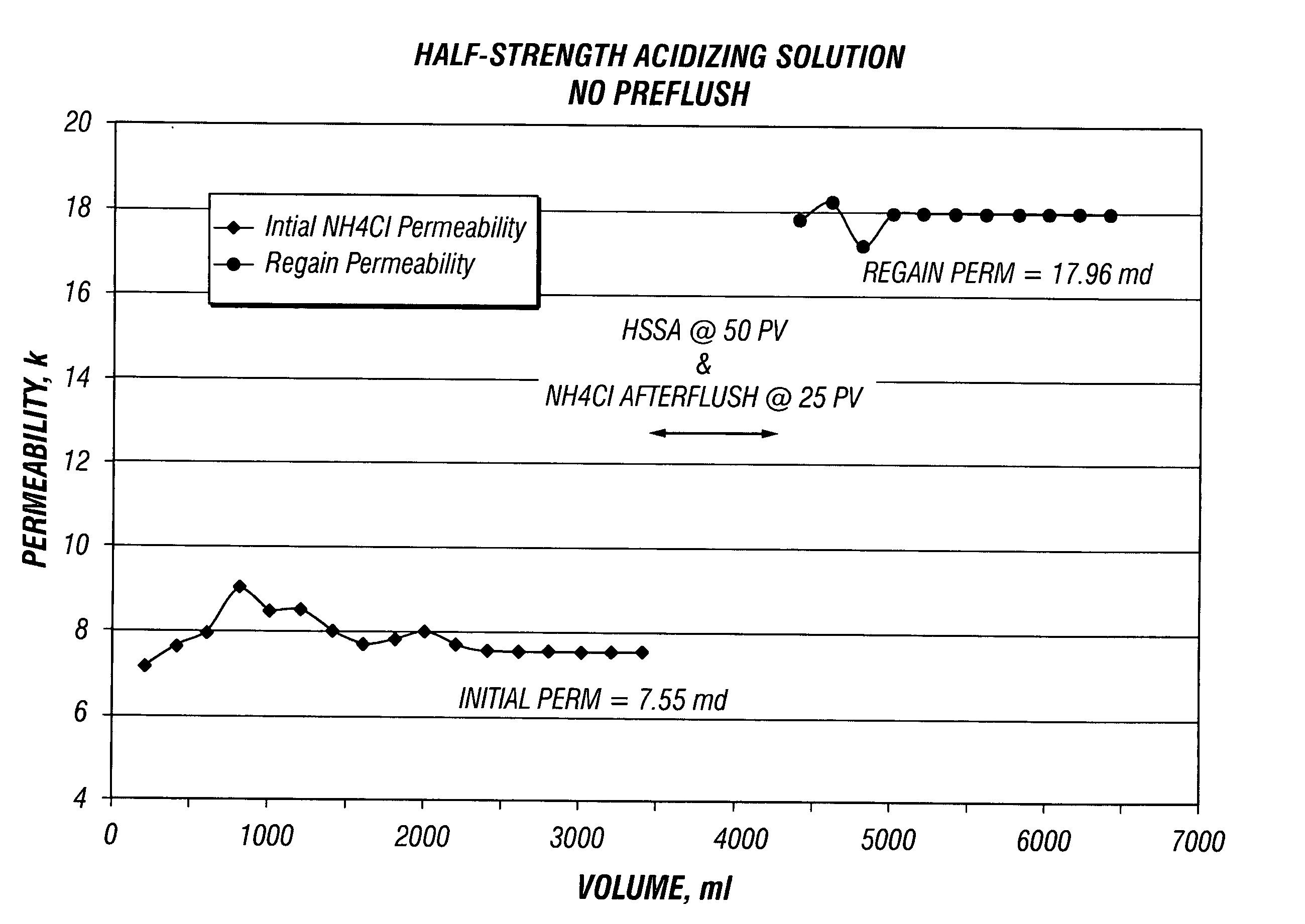
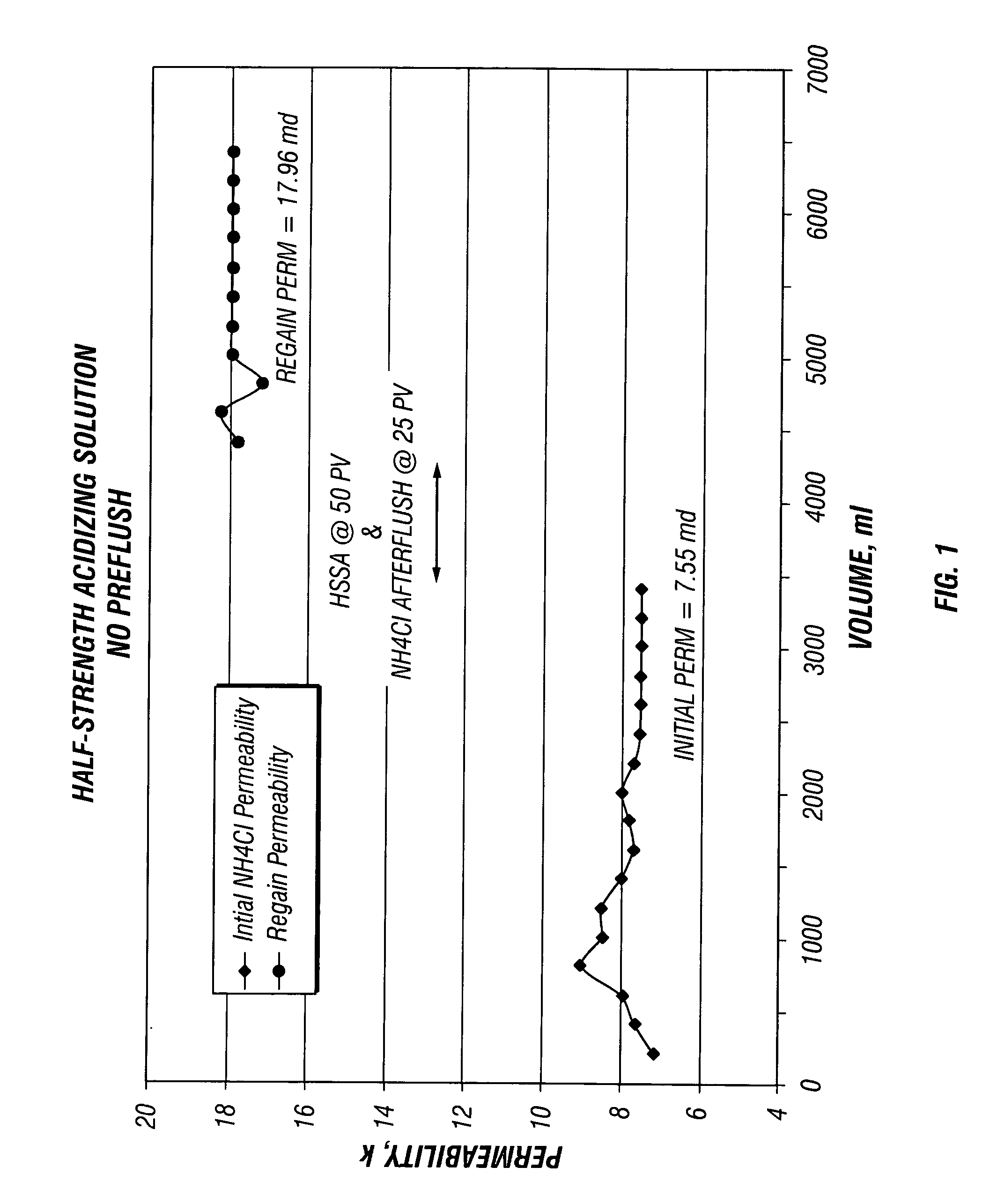
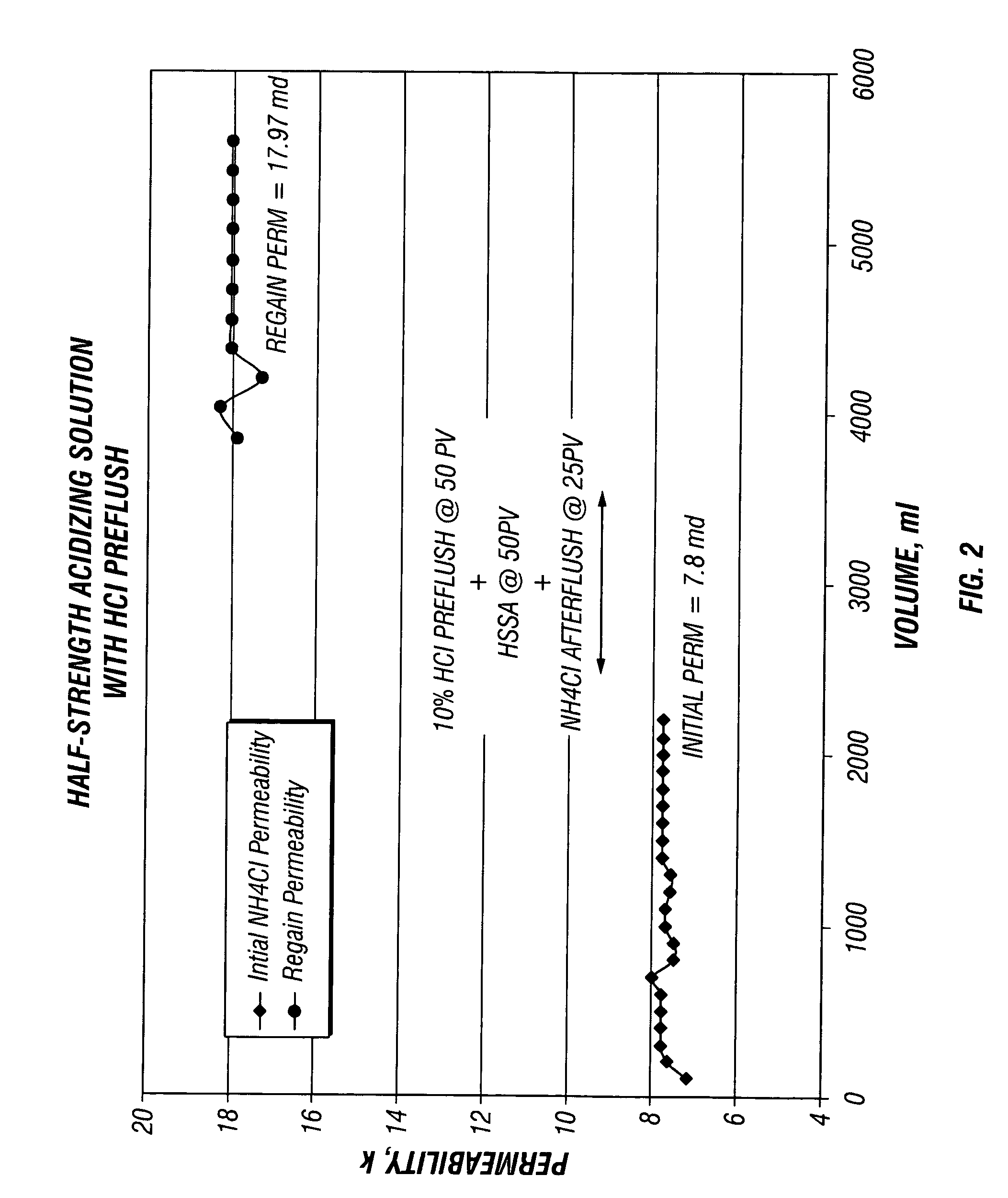
[0042] These Examples illustrate the effect of core flow testing using BJSSA on sandstone cores. Four separate core flow tests were conducted using 1.5 inch diameter and 2 inches length sandstone Berea core plugs with and without a preflush solution.

[0043] Prior to analysis, plugs were seated in rubber sleeves at 1000 psi confining pressure and flow saturated with filtered 3% NH4Cl containing a strongly water-wetting surfactant, NE-118 (a nonionic surfactant, a product of BJ Services Company) at 1 gpt. The surfactant was added to ensure that the sandstone was water wet and to avoid the formation of microemulsions.

[0044] The flow was established in an arbitrary formation to wellbore (production) direction with 3% NH4Cl brine to establish initial permeability. The flow was continued until a stable flow rate and permeability was obtained. [0045] 1. When flowing preflush, it was injected at 50 pore volumes in the reverse (injection) direction at constant flow rate of about 1 ml / min. W...


PUM


Abstract

Sandstone formations of oil and gas and geothermal wells are effectively stimulated when a buffered HF-sandstone acidizing solution is employed without the prior introduction of an acid containing preflush solution. By not using a preflush solution, buffered HF-sandstone acidizing solutions are highly effective in dissolving and removing siliceous material while minimizing the formation of calcium fluoride.

Description

[0001] This application claims the benefit of U.S. Patent Application Ser. No. 60 / 637,134, filed on Dec. 17, 2004.FIELD OF THE INVENTION [0002] The invention relates to a method of stimulating or remediating sandstone formations of oil and gas and geothermal wells without the use of preflush acidizing solutions. BACKGROUND OF THE INVENTION [0003] In the course of drilling, or during production or workover, the vast majority of oil and gas wells are exposed to conditions that ultimately lead to formation damage. Formation damage limits the productive (or injective) capacity of the well. The reduction in well performance is generally due to changes in near-wellbore permeability which may be caused by a number of factors, such as rock crushing, invasion of drill solids, swelling of pore-lining clays, migration of mobile fines and changes in wettability. [0004] It is known that permeability impairment may be improved by injecting acid formulations containing HF into the formation. Such ...

Claims


Application Information

Patent Timeline
IPC IPC(8): E21B43/27
CPCC09K8/72E21B43/25
Inventor RAE, PHILIP JAMESDI LULLO ARIAS, GINO F.AHMAD, ATIKAH JAMILAH BTE KUNJU
Owner BAKER HUGHES INC
Why Eureka
Try Eureka