Anaerobic biological wastewater treatment system and process

a biological wastewater and treatment system technology, applied in the direction of multi-stage water/sewage treatment, filtration separation, separation process, etc., can solve the problems of low yield of anaerobic microorganisms, limited design of three-phase separators, and extremely high limitations on hydraulic load of such separators, and achieve high volumetric efficiency

Active Publication Date: 2006-06-22
IND TECH RES INST
View PDF1 Cites 50 Cited by
  • Summary
  • Abstract
  • Description
  • Claims
  • Application Information

AI Technical Summary

Benefits of technology

[0014] The conventional anaerobic sludge bed treatment technique has the advantage of having a high volumetric efficiency on concentrated wastewater. However, when the concentration of organic matter in the wastewater is reduced, the anaerobic sludge bed treatment technique does not exhibit the desired efficiency due to limitations imposed by the hydraulic conditions. The present invention comb

Problems solved by technology

However, since anaerobic microorganisms have low yield, a key technical issue for an anaerobic sludge bed reactor is how to retain large quantities of anaerobic microorganisms in the reactor in order to optimize the performance of the anaerobic sludge bed reactor.
The conventional design of a three-phase separator is limited by the size of the anaerobic sludge bed reactor, and by the properties of t

Method used


Image

  • Anaerobic biological wastewater treatment system and process
  • Anaerobic biological wastewater treatment system and process
  • Anaerobic biological wastewater treatment system and process

Examples


example 1

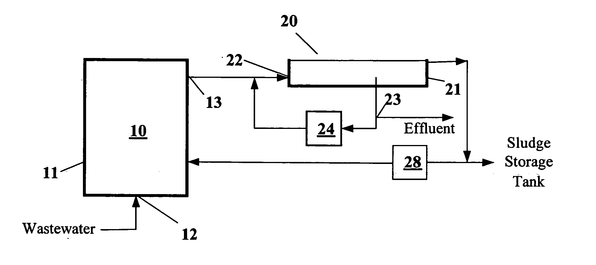
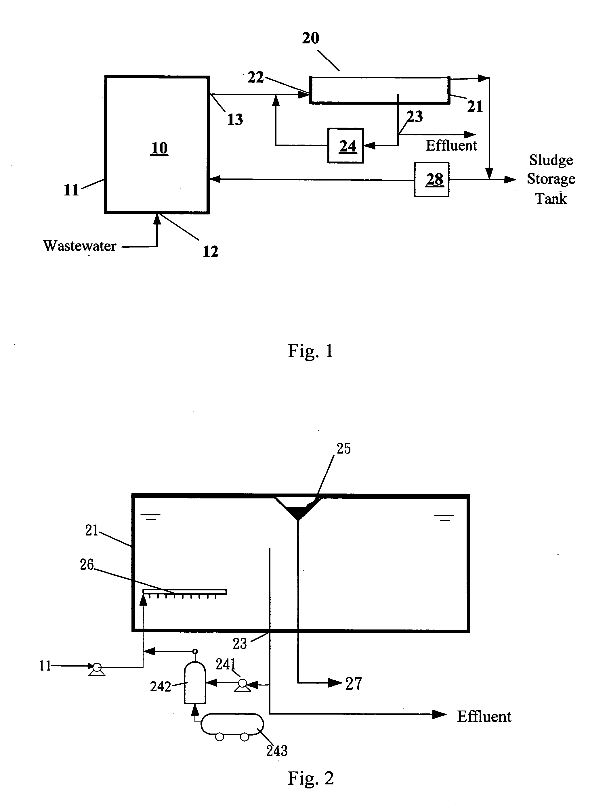
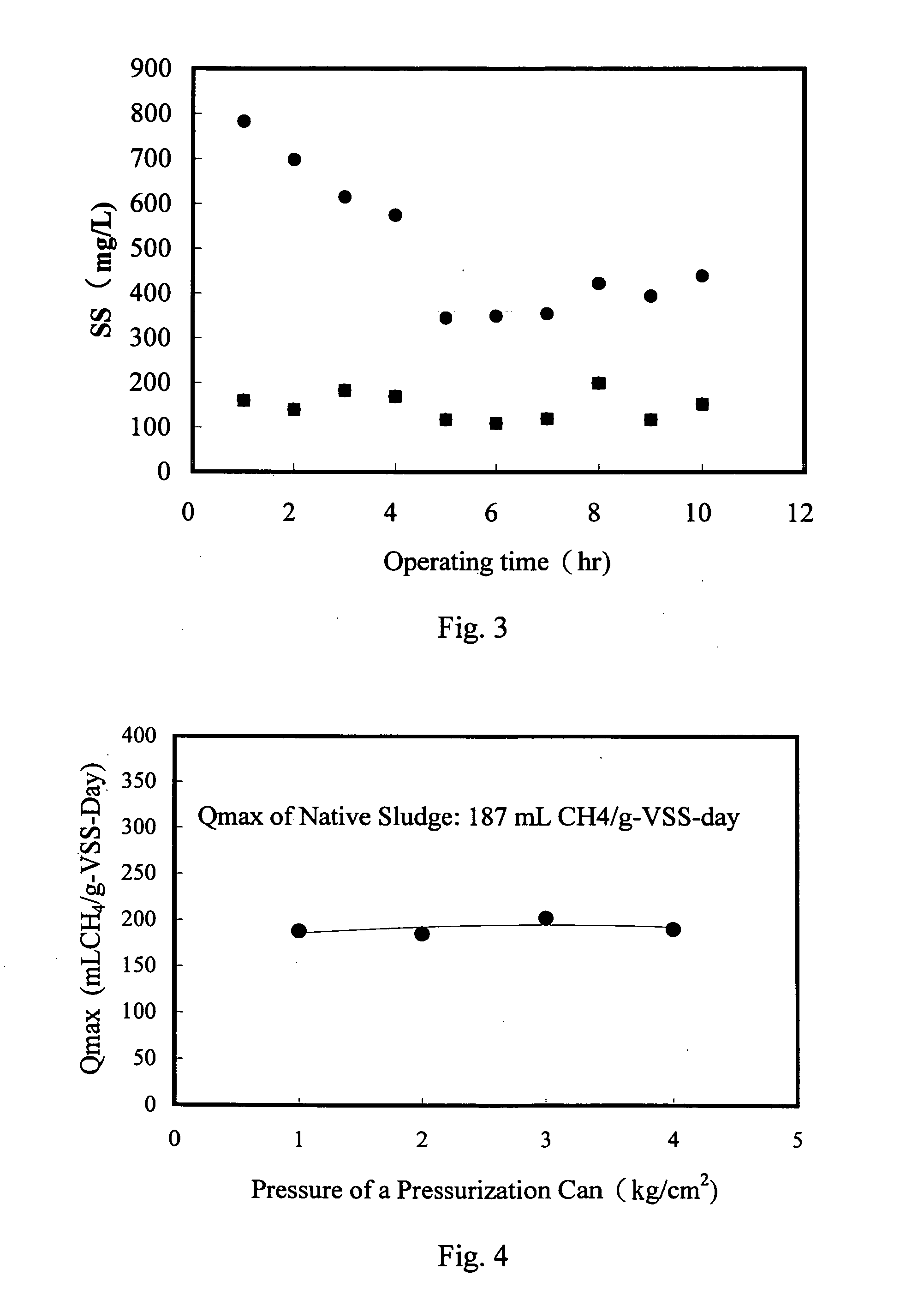
[0044] As shown in FIG. 1, the system of this example included an anaerobic sludge bed tank and a DAF tank. The system was tested in a food processing plant. The anaerobic sludge bed treatment tank used the UASB reaction tank of the food processing plant. The UASB was equipped with a three-phase separator with a hydraulic load of 16 m3 / m2-day. The UASB reaction tank had a volume of 390 m3, and a water treatment capacity of 1000 m3 / day. As shown in FIG. 2, the DAF tank included a tank body with a diameter of 1.2 meters. In this example, 120 L / min of water was pumped from the bottom the three-phase separator of the UASB reaction tank to perform a separation test of the DAF tank. The experimental process did not include a chemical reagent. The hydraulic load of the DAF tank was 150 m3 / m2-day, the pressure of the pressure tank was 4.5 kg / cm2, and the reflux flow was 50 L / min. The experimental results are shown in FIG. 3, wherein the concentration of the suspension solids (SS) of the inf...

example 2

[0046] This experiment was carried out in a batchwise procedure and included mounting an anaerobic sludge in a DAF tank and setting the pressure tank at different pressures (more oxygen being released at a higher pressures) to perform a flotation process for a specified period of time (10 minutes). The floatation concentrated sludge collected from the liquid surface of the DAF tank was measured by the same anaerobic microorganism activity measurement procedure in order to obtain a maximum methane production activity (Qmax) for the anaerobic microorganisms, and the obtained value was compared to the activity of the original sludge (un-floated).

[0047] A procedure for measuring the maximum methane production activity (Qmax) is described below. Microorganisms were loaded in an Erlenmeyer flask, and a quantitative amount of sodium acetate was added into the flask as an organic material. Next, nitrogen was introduced into the flask to flush out air therein, and subsequently the flask was...


PUM

PropertyMeasurementUnit
Pressureaaaaaaaaaa

Abstract

The present invention discloses an anaerobic biological wastewater treatment system for treating wastewater containing organic contaminants, which includes an anaerobic sludge bed reactor and a dissolved-air flotation tank. The anaerobic sludge bed reactor is used to decompose organic contaminants by way of an anaerobic biological treatment. The dissolved-air flotation tank is used to carry out liquid-solid separation on effluent from the anaerobic sludge bed reactor, so that anaerobic microorganisms entrained in the effluent can be recovered and recycled to the anaerobic sludge bed reactor, thereby enhancing the hydraulic loading of the anaerobic sludge bed reactor.

Description

FIELD OF THE INVENTION [0001] The present invention relates to an anaerobic biological wastewater treatment technique for treating wastewater containing organic contaminants, and in particular discloses an anaerobic biological wastewater treatment system and process that combines an anaerobic biological wastewater treatment technique with a dissolved-air flotation technique for treating wastewater that contains organic contaminants. BACKGROUND OF THE INVENTION [0002] Anaerobic biological wastewater treatment is one of the more common techniques in the treatment of wastewater that contains organic contaminants. An anaerobic sludge bed is the most commonly used reactor in anaerobic biological wastewater treatment. However, since anaerobic microorganisms have low yield, a key technical issue for an anaerobic sludge bed reactor is how to retain large quantities of anaerobic microorganisms in the reactor in order to optimize the performance of the anaerobic sludge bed reactor. At present...

Claims


Application Information

Patent Timeline
IPC IPC(8): C02F3/28C02F1/24
CPCC02F1/24C02F3/2846
Inventor YOU, HUEY-SONGCHOULIEN, SHUI-CHENWU, WUNG-JUNGLIN, HSIN-JUNG
Owner IND TECH RES INST
Why Eureka
Try Eureka