Energy conversion device and production method therefor

a technology of energy conversion device and production method, which is applied in the direction of instruments, non-electron emission shielding screens, tobacco, etc., can solve the problems of inability to convert energy into visible radiation without a lot of infrared rays, wavelengths too long to sense with human eyes, and expense of visible radiation, etc., to achieve high luminous efficacy, long life, and increase the ratio of visible radiation to infrared radiation

Inactive Publication Date: 2006-06-22
PANASONIC CORP
View PDF1 Cites 19 Cited by
  • Summary
  • Abstract
  • Description
  • Claims
  • Application Information

AI Technical Summary

Benefits of technology

[0025] According to the present invention, an energy converter, which may function as a filament for an incandescent lamp, for example, includes a woven or knitted metal wire mesh as a radiation cut means for cutting down electromagnetic radiations, of which the wavelengths exceed a predetermined wavelength, such that the radiation cut means faces the electromagnetic radiation emitting side of a heat source. Thus, the infrared radiations from the heat source can be cut down for a long time and the ratio of visible radiations to the infrared radiations can be increased in an incandescent lamp. As a result, a light bulb with high luminous efficacy and practically long life can be provided.
[0026] In addition, the radiation cut means is implemented as a woven or knitted mesh of metal wires, and therefore, exhibits good thermal stability. Furthermore, the aperture size of the mesh openings does not change significantly even if the temperature varies. Consequently, high radiation efficiency can be maintained with good stability.

Problems solved by technology

One of major obstacles that prevent an artificial light source from achieving high luminous efficacy is that the light source cannot convert energy into visible radiation without radiating a lot of infrared rays, of which the wavelengths are too long to sense with human eyes, at the expense of the visible radiation.
This performance of the incandescent lamps has not been improved significantly since 1930's.

Method used


Image

  • Energy conversion device and production method therefor
  • Energy conversion device and production method therefor
  • Energy conversion device and production method therefor

Examples


embodiment 1

[0038] First, a first preferred embodiment of an energy converter according to the present invention will be described with reference to FIG. 4.

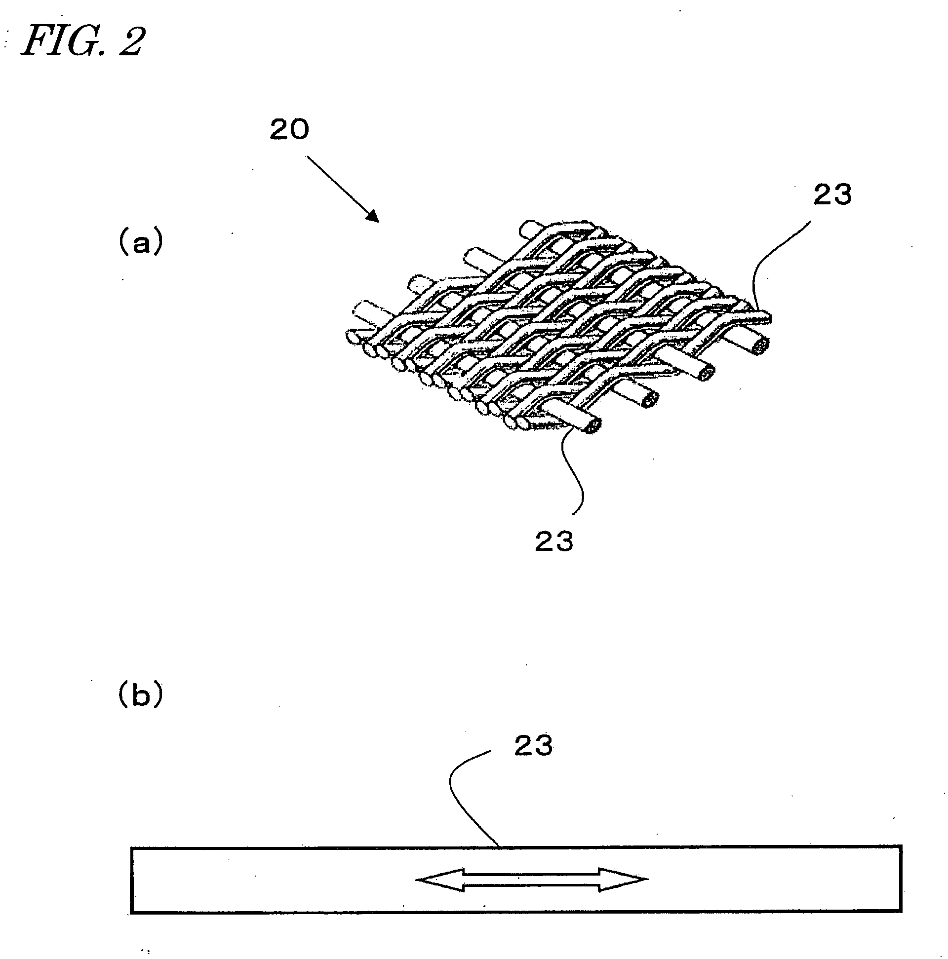
[0039] The energy converter of this preferred embodiment shown in FIG. 4 includes a heat source that emits electromagnetic radiations when heated to a high temperature (which will be referred to herein as a “radiator 1”) and a radiation cut means provided around the radiator 1. In this preferred embodiment, the structure functioning as the radiation cut means is a mesh 2 obtained by weaving tungsten fine wires together.

[0040] The radiator 1 is usually preferably made of a material that can be used as a filament for an incandescent lamp. However, the “radiator” is not limited herein to the filament that generates heat and emits light in a normal incandescent lamp. Nevertheless, if the energy converter of the present invention is used in an illumination source, then the radiator may be made of a known filament material used in an ordinary in...

embodiment 2

[0064] Hereinafter, a second preferred embodiment of an energy converter according to the present invention will be described with reference to FIG. 6.

[0065] In the preferred embodiment illustrated in FIG. 6, the radiation cut means is implemented as a stack of multiple meshes 2. Each of these meshes 2 may have a configuration just as described for the first preferred embodiment. In this preferred embodiment, the meshes 2 are stacked one upon the other such that associated openings of all those meshes 2 stacked are aligned with each other. In this manner, the openings functioning as the waveguides (i.e., micro-cavities) can have a substantially increased depth (i.e., waveguide length). Accordingly, even if the stack of meshes 2 is arranged a little distant from the radiator 1 but if the depth of the openings of the meshes 2 is at least 1.5 times as large as the aperture size of the meshes 2, then the emissivity of the visible radiation through the openings of the meshes 2 can be in...


PUM


Abstract

An energy converter according to the present invention includes a heat source (radiator 1), which receives externally applied energy and raises its temperature, thereby emitting electromagnetic radiations, and a radiation cut portion (mesh 2) for cutting down infrared radiations, of which the wavelengths are longer than a predetermined wavelength. The mesh 2 is a woven or knitted mesh of metal wires. The openings of the woven or knitted mesh have an aperture size that is smaller than the predetermined wavelength.

Description

TECHNICAL FIELD [0001] The present invention relates to an energy converter and a method of making the same, and more particularly relates to an illumination source that can exhibit high luminous efficacy with infrared radiations cut down. BACKGROUND ART [0002] One of major obstacles that prevent an artificial light source from achieving high luminous efficacy is that the light source cannot convert energy into visible radiation without radiating a lot of infrared rays, of which the wavelengths are too long to sense with human eyes, at the expense of the visible radiation. [0003] An incandescent lamp needs no ballasts, has a small size and a light weight, and shows a higher color rendering index than any other artificial light source. Due to these advantageous features, the incandescent lamp is a light source that is used most broadly worldwide. To increase the radiation efficiency of incandescent lamps, people tried to raise the operating temperature of the radiator or to find a ra...

Claims


Application Information

Patent Timeline
Patent Type & Authority Applications(United States)
IPC IPC(8): H01J21/10G02B5/00G02B5/20
CPCG02B5/003G02B5/204G02B5/208
Inventor HORIUCHI, MAKOTOKIMOTO, MITSUHIKOOHKUBO, KAZUAKIKANEKO, YURIKOSAKAUE, MIKA
Owner PANASONIC CORP
Why Eureka
Try Eureka