
Direct method for the correction of pressure induced scrambling of polarized fluorescence intensities

a fluorescence intensity and pressure-induced technology, applied in the direction of fluorescence/phosphorescence, optical radiation measurement, instruments, etc., can solve the problems of significant distorted determined values of fluorescence emission anisotropy (ea), inherent scrambling of polarized light, and experimentally challenging approaches

Inactive Publication Date: 2006-06-22
DAVENPORT LESLEY +1
View PDF2 Cites 0 Cited by
  • Summary
  • Abstract
  • Description
  • Claims
  • Application Information

AI Technical Summary

Benefits of technology

This method provides accurate, real-time correction of fluorescence anisotropy and total intensity measurements under high pressure without the need for additional calibration, minimizing experimental complexity and reducing errors due to window aging and pressure-induced artifacts.

Problems solved by technology

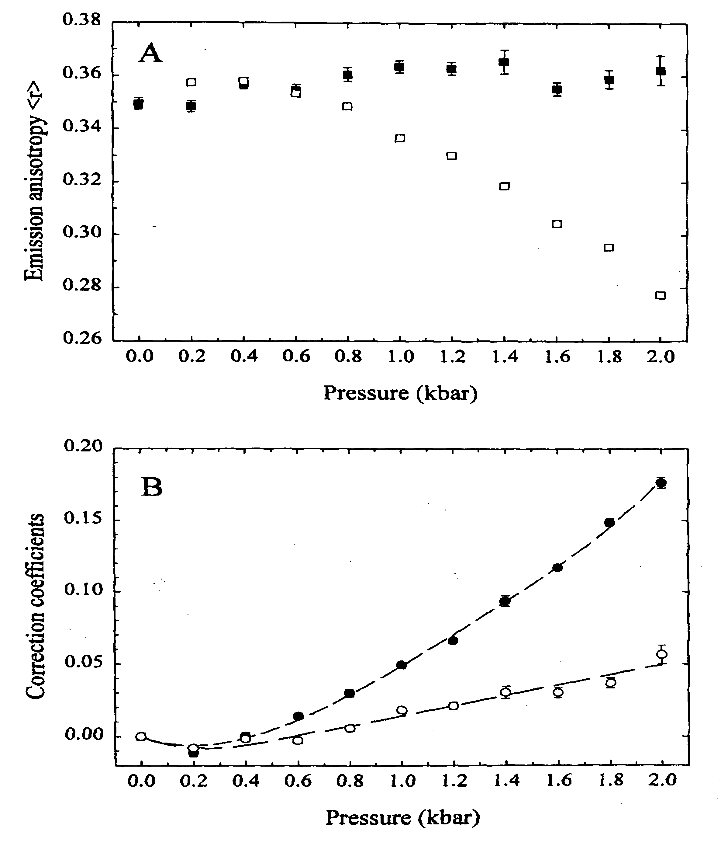
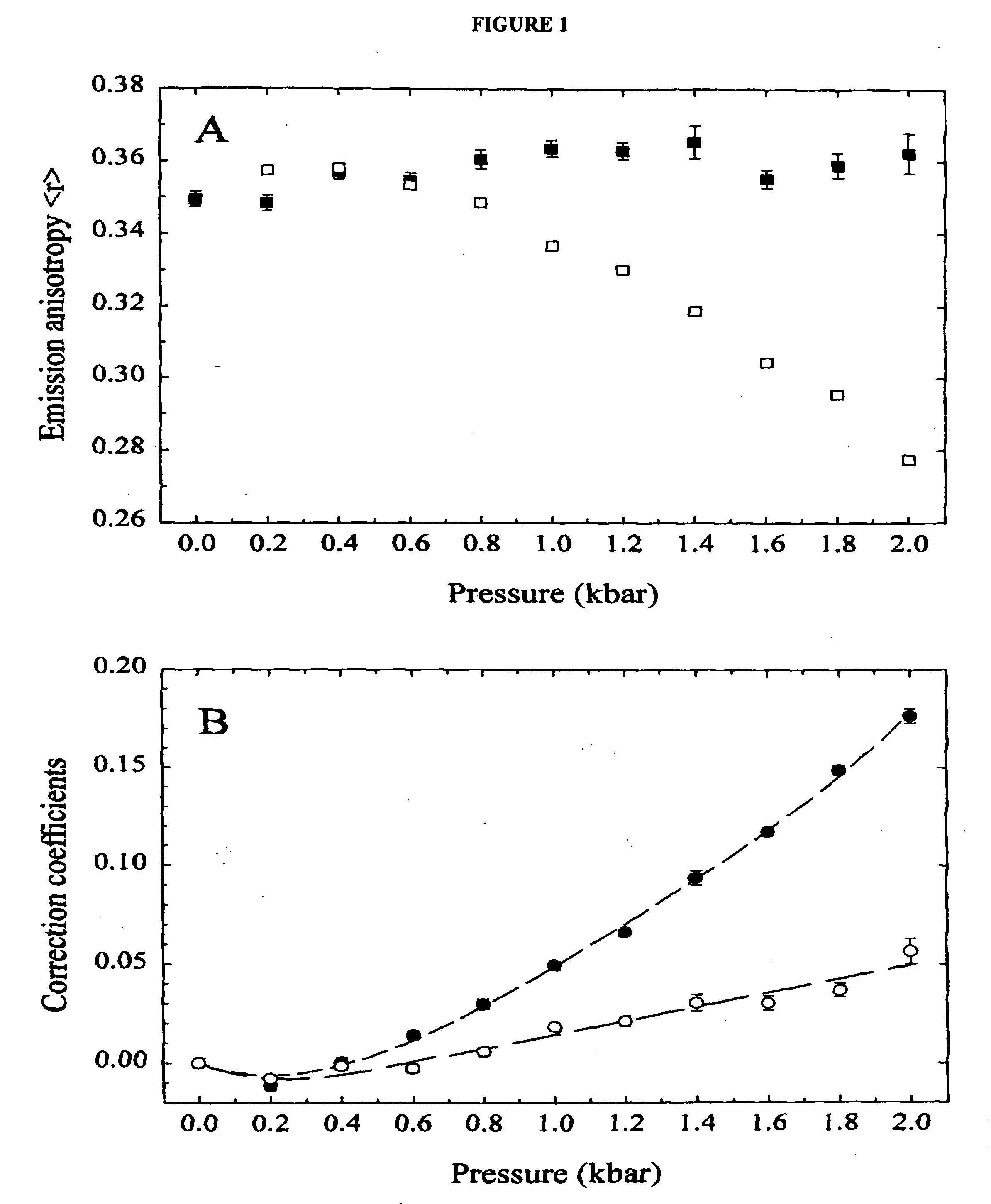
However, a severe limitation of this approach is the inherent scrambling of the polarized light by the induced birefringence of the optical windows (quartz or to a lesser extent, sapphire) of the spectroscopy cell when pressures of greater than 0.2 kbar are applied.
As a result, measured polarized fluorescence intensities are contaminated by scrambling artifacts, and determined values of the fluorescence emission anisotropy (EA) are significantly distorted.
However, this approach is experimentally challenging as the polarizing material must be sandwiched between quartz plates, and sealed to exclude possible deleterious effects of the pressure transducing fluid (usually ethanol).
This approach can lead to instrumental problems involving the matching of the photomultiplier responses of the two detection arms, or alternatively requires the use of optical fibers to transmit emission intensities from the high pressure spectroscopy cell via more conventional L-configuration optics.

Method used


Image

  • Direct method for the correction of pressure induced scrambling of polarized fluorescence intensities
  • Direct method for the correction of pressure induced scrambling of polarized fluorescence intensities
  • Direct method for the correction of pressure induced scrambling of polarized fluorescence intensities

Examples


example 1

[0086] The present method of correction has been tested for common fluorescent dyes 1,6-diphenyl-1,3,5-hexatriene (DPH) and 9,10-diphenylanthracene (DPA) in glycerol where their rotational behavior is well understood. In addition, the pressure induced>melt=profile for the more complicated biologically relevant system of DPH imbedded within dipalmitoylphosphatidylcholine (DPPC) small unilamellar vesicles (SUVs), has been reexamined.

Materials

[0087] 9,10-Diphenylanthracene (DPA) was purchased from Aldrich Chemical Co. (Milwaukee, Wis.) and 1,6-diphenyl-1,3,5-hexatriene (DPH) was obtained from Molecular Probes, Inc. (Eugene, Oreg.). Both fluorescent dyes were used as supplied. Glycerol (Omnisolv; 99.84%) with UV cut-off of 203 nm, was purchased from EM Science (Gibbstown, N.J.). Absolute ethanol (200 proof; Gold Shield) was supplied by Commercial Solvents Corporation (Terre Haute, Ind.). L-α-dipalmitoylphosphatidylcholine (DPPC) was purchased from Sigma Chemical Company (St Louis, Mi...

example 2

Derivation of Equations

[0109] A.1. Standard Instrument Description: Polarized or partially polarized light may be completely described via a four component Stokes vector (See reference 30, infra.): I=[IMCS]=I·[lmcs]=[<⁢mx2⁡(t)+my2⁡(t)⁢><⁢mx2⁡(t)-my2⁡(t)⁢><⁢2⁢mx⁡(t)⁢my⁡(t)⁢cos⁢ ⁢δ⁢><⁢2⁢mx⁡(t)⁢my⁡(t)⁢sin⁢ ⁢δ⁢>](A⁢.1)

where mx and my are amplitudes (with relative phase shift δ) of the electric field in directions x and y, respectively. It is assumed that the x direction lies parallel with the experimental plane and will be referred to as the horizontal (H) component, whereas the y direction, perpendicular to the experimental plane, is assigned as vertical (V). It is also assumed that the absorption and subsequent fluorescence emission of a fluorophore arise exclusively from electric dipole transitions and are not sensitive to any rotations by the electromagnetic field. Furthermore, it is assumed that the fluorescence instrument considered here is equipped wit...


PUM

PropertyMeasurementUnit
emission wavelengthaaaaaaaaaa

Abstract

The present invention provides a simple and direct method for the simultaneous correction of steady-state polarized fluorescence intensities, depolarized (or scrambled) by the effects of applied hydrostatic pressure without having to first determine the scrambling factors from a separate experiment. The method involves direct recalculation of the measured polarized data obtained for the sample of interest at the time of data collection.

Description

CROSS REFERENCE TO RELATED APPLICATIONS [0001] This application is a divisional of U.S. application Ser. No. 09 / 659,412, filed Sep. 11, 2000, which claims benefit of U.S. Provisional Application Ser. No. 06 / 153,488, filed Sep. 11, 1999, the content of which is incorporated by reference herein in its entirety.FIELD OF THE INVENTION [0002] The present invention is directed to methods for the direct and simultaneous correction of steady-state polarized fluorescence intensities, depolarized (or scrambled) by the effects of applied hydrostatic pressure. The present methods eliminate the requirement of first determining the scrambling factors from a separate experiment with a dye immobilized in a rigid medium. Rather, in accordance with the present methods, correction for depolarizing effects of windows under a pressure differential, such as high pressure spectroscopy cell windows, is achieved by direct recalculation of the measured polarized data obtained for the sample of interest at th...

Claims


Application Information

Patent Timeline
Patent Type & Authority Applications(United States)
IPC IPC(8): G01J3/30A61B5/00G01J3/44G01J4/00G01N21/64
CPCG01J3/4406G01N21/6445
Inventor DAVENPORT, LESLEYTARGOWSKI, PIOTR
Owner DAVENPORT LESLEY
Learn More