Particle detection system implemented with an immersed optical system

Active Publication Date: 2006-06-22
HACH CO
View PDF15 Cites 21 Cited by
  • Summary
  • Abstract
  • Description
  • Claims
  • Application Information

AI Technical Summary

Benefits of technology

[0006] Preferred embodiments of the invention improve light collection and image quality from a collection system of a fluid particle detection system by using immersed optics on a flow-through cell for collecting and detecting scattered light from particles. The particle detection system is capable of optically detecting particles in a fluid stream and includes a flow chamber within which a light beam propagating along a light propagation path and a fluid stream containing sample particles transversely intersect to form a v

Problems solved by technology

An increase in the amount of light collected results in an increase i

Method used


Image

  • Particle detection system implemented with an immersed optical system
  • Particle detection system implemented with an immersed optical system
  • Particle detection system implemented with an immersed optical system

Examples


Example

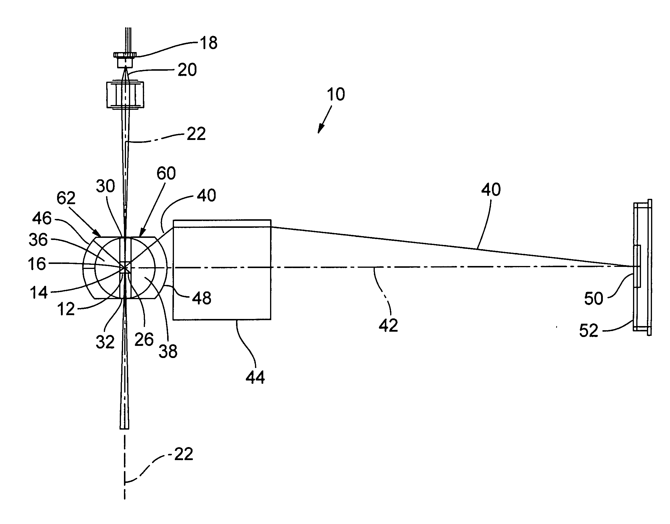
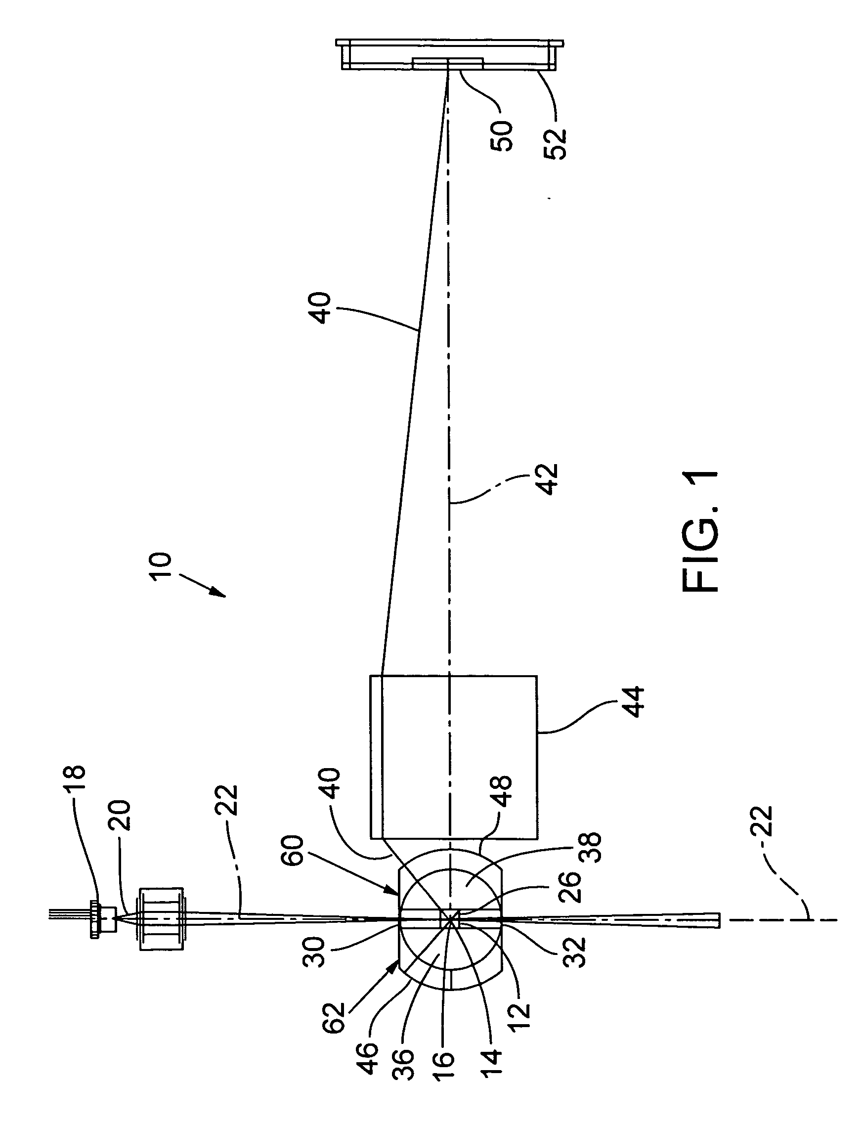
[0020]FIG. 1 is useful in explaining the configuration of an exemplary particle detection system 10. Particle detection system 10 includes a flow chamber 12 (extending out of the plane of FIG. 1) through which a particle-carrying sample fluid stream 14, such as gas (e.g., air) or liquid (e.g., water), flows in a flow direction 16 (out of the plane of FIG. 1). Particle detection system 10 also includes a light source 18 emitting a light beam 20 that propagates in a direction along an optical axis 22. Light source 18 is preferably a diode laser that is robust, efficient, and compact. Exemplary preferred light sources are gas, dye, and solid-state lasers.

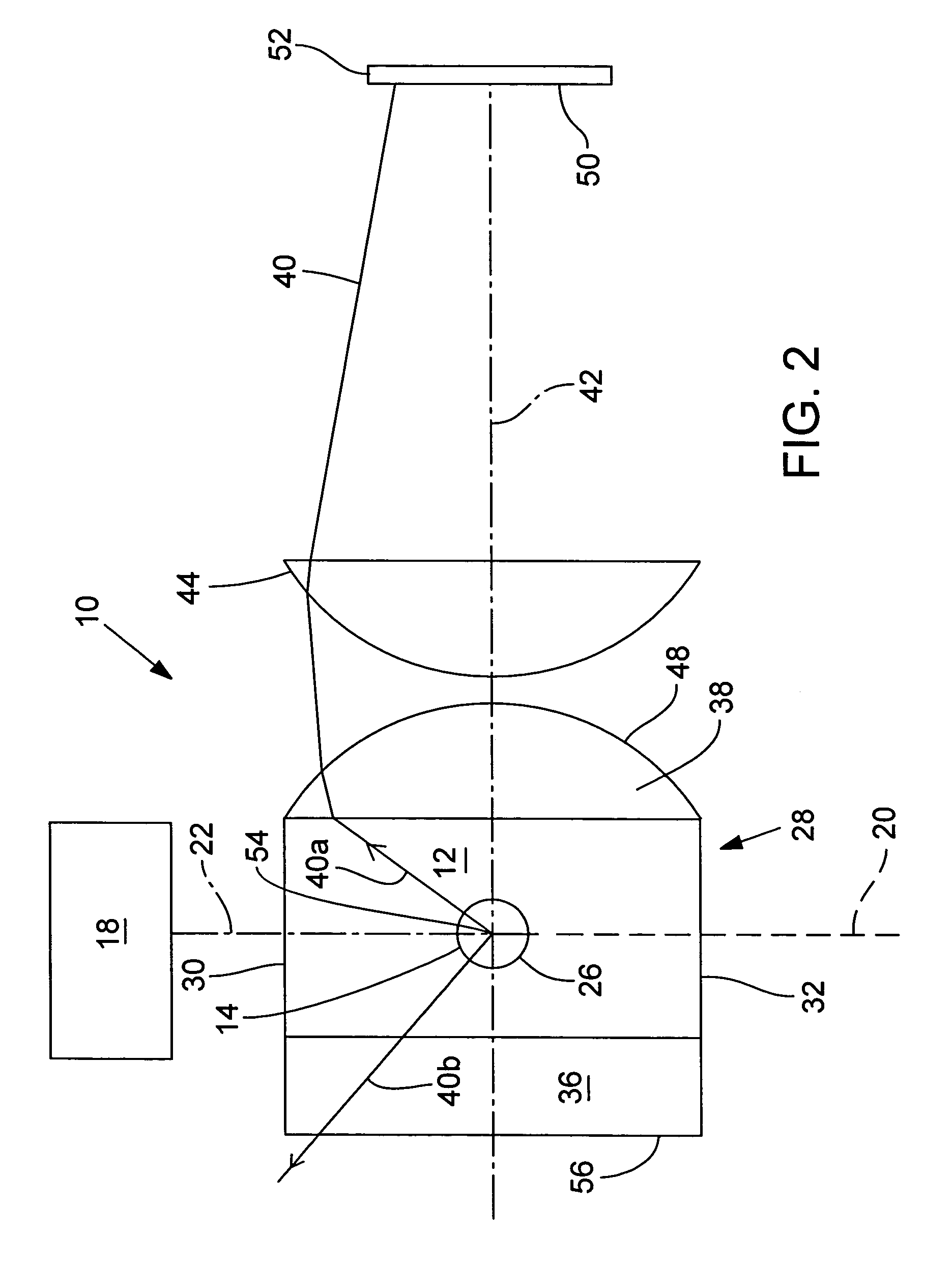
[0021] Fluid stream 14 and light beam 20 intersect within the effective center of flow chamber 12 in a region called a view volume 26. View volume 26 is located within a unitary flow-through cell 28 that includes first and second spaced-apart, opposed optically transparent windows 30 and 32 through which light beam 20 propagates into ...


PUM


Abstract

Fluid-based particle detection exhibits improved light collection and image quality from a light collection system that uses immersed optics on a flow-through cell for collecting and detecting scattered light from particles carried by the fluid.

Description

RELATED APPLICATIONS [0001] This application is a continuation-in-part of U.S. patent application Ser. No. 10 / 927,671, filed Aug. 27, 2004, for PARTICLE DETECTION SYSTEM, which is a continuation of U.S. patent application Ser. No. 10 / 407,650, filed Apr. 4, 2003, now U.S. Pat. No. 6,784,990, for PARTICLE DETECTION SYSTEM IMPLEMENTED WITH A MIRRORED OPTICAL SYSTEM.TECHNICAL FIELD [0002] The present invention relates to optical particle detection and, in particular, to a particle detection system with increased sensitivity in the detection of submicron-diameter particles. BACKGROUND INFORMATION [0003] Contamination control, including particle monitoring, plays a critical role in the manufacturing processes of several industries. These industries require clean rooms or clean zones with active air filtration and require the supply of clean raw materials such as process gases, deionized water, chemicals, and substrates. In the pharmaceutical industry, the U.S. Food and Drug Administration...

Claims


Application Information

Patent Timeline
IPC IPC(8): G01N21/00
CPCG01N15/1459G01N21/94G01N2015/1493
Inventor GIRVIN, KENNETH L.DEFREEZ, RICHARD K.BRADY, JAMES
Owner HACH CO
Why Eureka
Try Eureka