Optical apparatus

a technology of optical apparatus and fiber laser, which is applied in the direction of electrical apparatus, instruments, etc., can solve the problems of easy ruggedization, limit the number and type of pump sources, and end pumping approach for injecting optical pump power, etc., to achieve simple, efficient and low cost, facilitate high-power pump injection into the active fiber, and reduce size and alignment sensitivity

Inactive Publication Date: 2006-06-22
STATE OF ISRAEL - SOREQ NUCLEAR RES CENT
View PDF6 Cites 18 Cited by
  • Summary
  • Abstract
  • Description
  • Claims
  • Application Information

AI Technical Summary

Benefits of technology

[0014] The present invention seeks to provide simple, efficient and low cost side-coupling apparatus between a pump source and an active double clad fiber, useful for side pumping of high power fiber lasers and amplifiers. The invention may comprise a direct side coupling, employing leaky guiding mode coupling from a pump guiding fiber to a receiving active fiber, which may be a fiber laser or an optical amplifier. The side coupling may comprise a tapered fiber, as is described more in detail hereinbelow. The invention may reduce size and alignment sensitivity, and facilitate high power pump injection into the active fiber. The coupling technique of the present invention is much more robust, less expensive, more efficient than traditional end pumping techniques and more efficient and scalable to high powers than prior art side coupling, such as that of Samartsev et al.

Problems solved by technology

In addition, they may be easily ruggedized, due to their simple arrangement.
One of the problems in double clad fibers, used for high power fiber laser applications, is the end pumping approach for injecting optical pump power.
This physical limit constrains the number and type of pump sources that may be used to inject the optical power.
In addition, when the double clad fiber is used as a power amplifier, end pumping prohibits simple injection of the signal to be amplified, and renders the coupling optics cumbersome and expensive.
One of the main limitations today in using high power fiber lasers and amplifiers is, however, the pump coupling technique.
However, the end pumping technique may limit coupling efficiency, lower the fiber laser system robustness, due to the complex optics alignment and tight tolerances required, and also increase the system cost, due to the expensive optics used.
The problem becomes even more severe when high power fiber amplification is required.
The complex alignment and tight tolerances, along with the high power flux at the fiber input end, render this configuration complex, inefficient, expensive and very sensitive to environmental changes.
Another disadvantage of Samartsev et al. is that when using fibers with k<=1, (that is, the divergence angles of the pump guiding fiber is higher or equal to that of the inner cladding of the double clad fiber) where the fusion region is only the tapered region of the pump-guiding fiber, than the pump coupling efficiency between the pump guiding fiber and the inner cladding of the double clad fiber is low and renders the Samartsev et al. method inefficient.

Method used


Image

  • Optical apparatus
  • Optical apparatus
  • Optical apparatus

Examples


Embodiment Construction

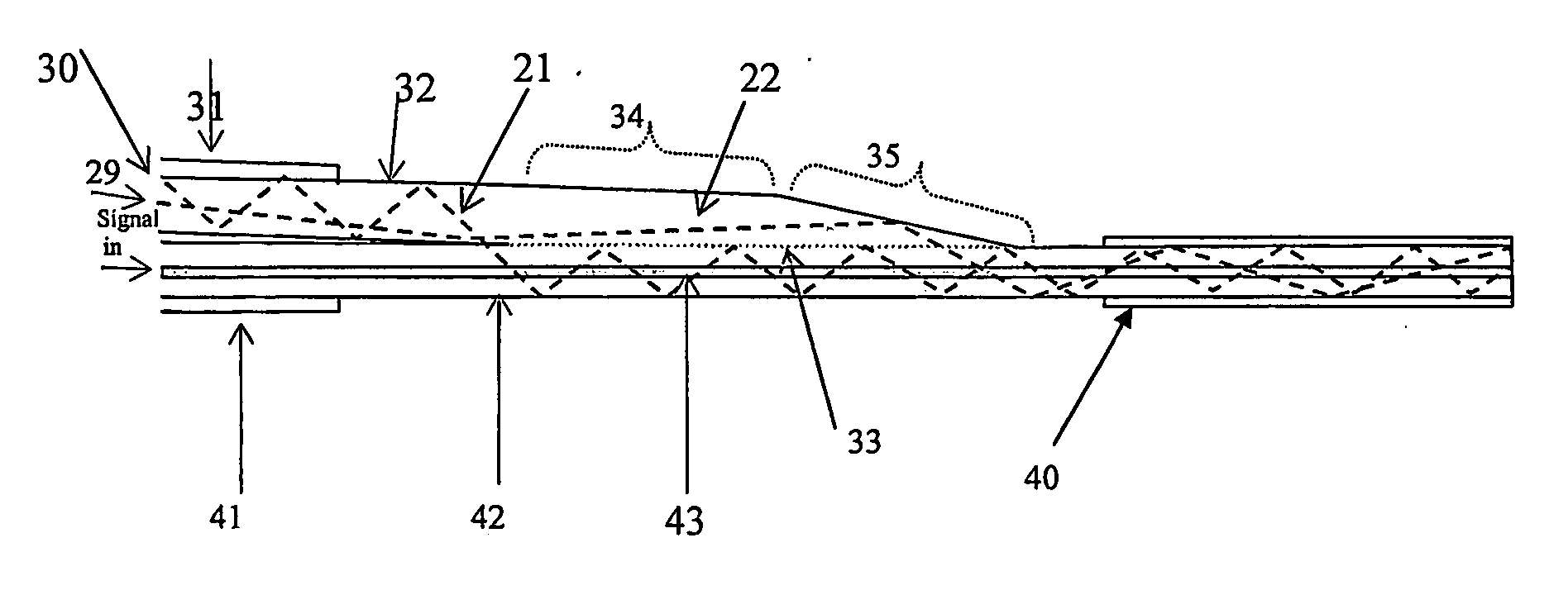
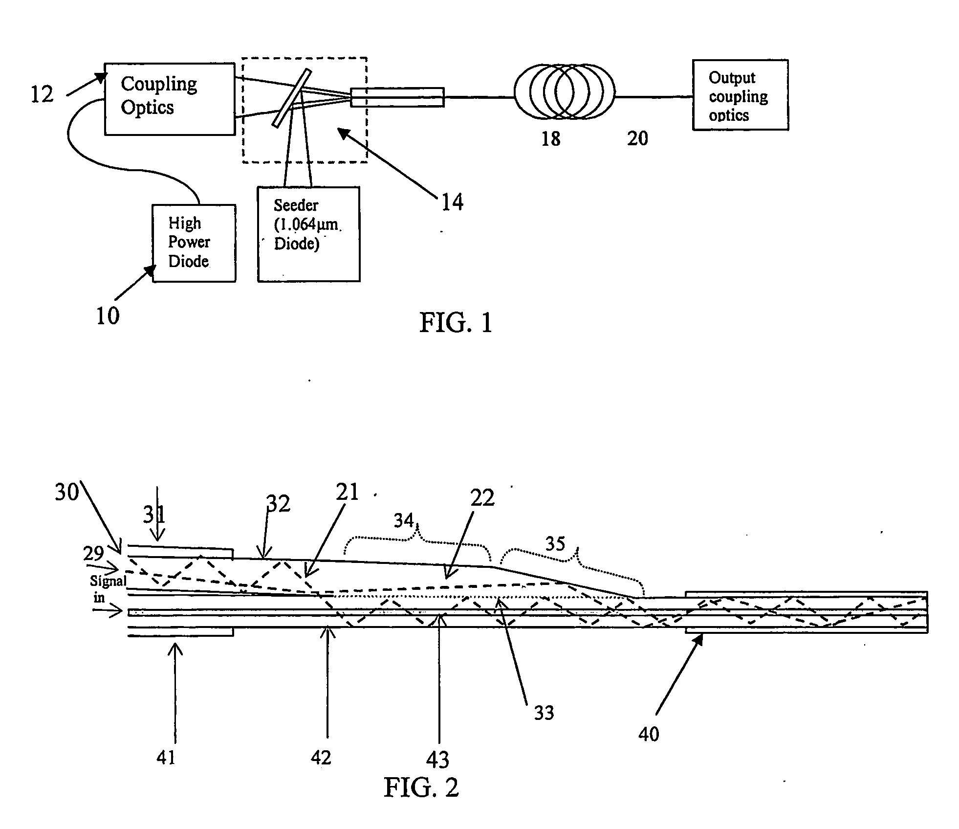
[0022] Reference is now made to FIG. 2, which illustrates a side coupling for a fiber laser or optical amplifier, such as a high power double clad fiber laser or amplifier, constructed and operative in accordance with an embodiment of the present invention.

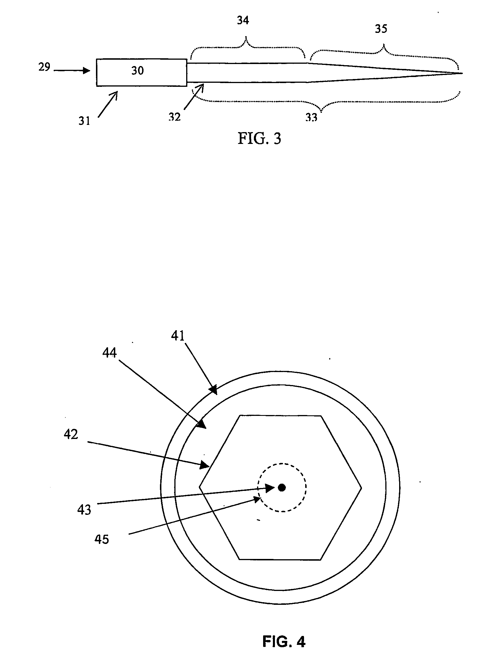
[0023] A pump-guiding fiber 30 may comprise a fiber cladding 31, a fiber core 32 and an attachment section 33. As seen in FIG. 3, the fiber core 32 is exposed by stripping the fiber cladding 31 along the attachment section required 33. The attachment section 33 may comprise a straight core section 34 and a tapered core section 35. The ratio between the minimum cross section area of the tapered region and the initial cross section area thereof is from 0.01 to 0.5. The pump-guiding fiber 30 may be optically attached at one end thereof to a pump source 29, such as but not limited to, a semiconductor diode laser. The opposite end of pump-guiding fiber 30, which comprises the attachment section 33, may be attached to an inner clad 42 ...


PUM


Abstract

Optical apparatus comprising a pump guiding fiber comprising a fiber cladding, a fiber core and an attachment section, the attachment section comprising a straight core section and a tapered core section, and a receiving fiber comprising an inner clad to which the attachment section is attached.

Description

FIELD OF THE INVENTION [0001] The present invention relates to side pumping of fiber lasers and amplifiers, such as high power fiber lasers and amplifiers. BACKGROUND OF THE INVENTION [0002] High power fiber lasers have become increasingly popular due to their high efficiency, simplicity and reliability. In addition, they may be easily ruggedized, due to their simple arrangement. [0003] High power applications generally use a double clad fiber. This fiber comprises a core, usually doped with a lasing material such as rare earth ions or other, an inner cladding encircling the doped core, through which the pump power flows and is gradually absorbed in the doped core, and an outer cladding the inner cladding and forming a dielectric wave guide for the pump signal. The optical characteristics of the inner cladding closely match high power diode lasers, commonly used for solid-state laser pumping. Therefore, highly efficient pumping may be achieved by utilizing double clad fibers as a ga...

Claims


Application Information

Patent Timeline
Patent Type & Authority Applications(United States)
IPC IPC(8): G02B6/26G02B6/02G02B6/00G02B6/42G02B6/28H01S3/094
CPCG02B6/2804G02B6/2852H01S3/06729H01S3/094003H01S3/094007H01S3/094019H01S3/094053H01S3/0941
Inventor SINTOV, YOAV
Owner STATE OF ISRAEL - SOREQ NUCLEAR RES CENT
Why Eureka
Try Eureka