Belt drive controlling method, belt drive controlling apparatus, belt apparatus, image forming apparatus, and computer product

a technology of control apparatus and belt drive, applied in the direction of electrographic process apparatus, instruments, optics, etc., can solve the problems of small deviation of belt, inability to suppress and difficulty in suppressing the following minute velocity fluctuation

Inactive Publication Date: 2006-06-22
RICOH KK
View PDF9 Cites 23 Cited by
  • Summary
  • Abstract
  • Description
  • Claims
  • Application Information

AI Technical Summary

Problems solved by technology

It has long been believed that such small deviations of the belt cannot be suppressed.
However, it has been thought that the deviation amount of the fluctuated belt position that can be controlled by the pulse motor is in a range of at least a deviation amount corresponding to a belt moving amount per one driving pulse signal and a fluctuation amount of position smaller than the belt moving amount cannot be adjusted.
According to the conventional concept, it has been thought that it is difficult to suppress the following minute velocity fluctuation.
An expensive driver is generally required for the micro-step exceeding a reduction ratio of 1 / 8, or a reduction mechanism with a high reduction ratio must be constituted using a gearwheel with a large diameter or it needs to have a multi-tier configuration.
Accordingly, realization of such a large reduction ratio as about 1 / 2100 causes cost elevation and requires a large space for storing equipment, and therefore, it is unrealistic.

Method used


Image

  • Belt drive controlling method, belt drive controlling apparatus, belt apparatus, image forming apparatus, and computer product
  • Belt drive controlling method, belt drive controlling apparatus, belt apparatus, image forming apparatus, and computer product
  • Belt drive controlling method, belt drive controlling apparatus, belt apparatus, image forming apparatus, and computer product

Examples


first embodiment

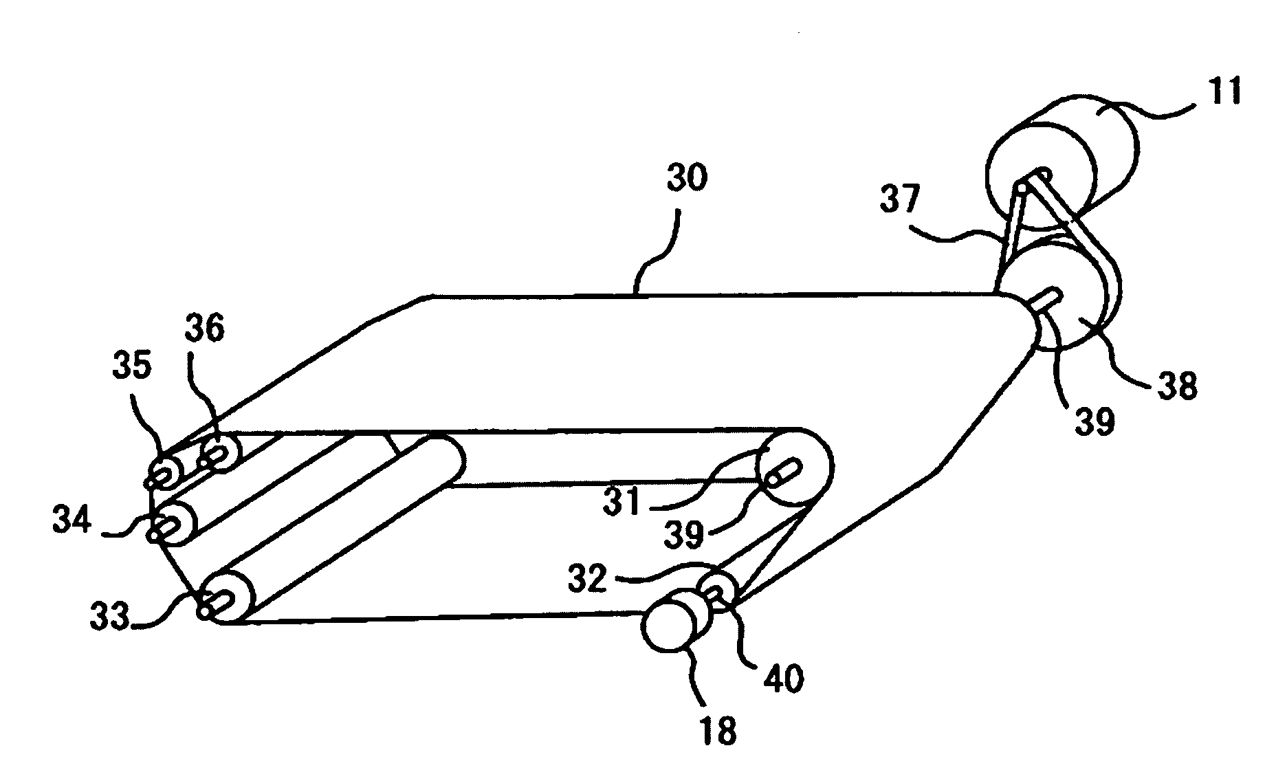
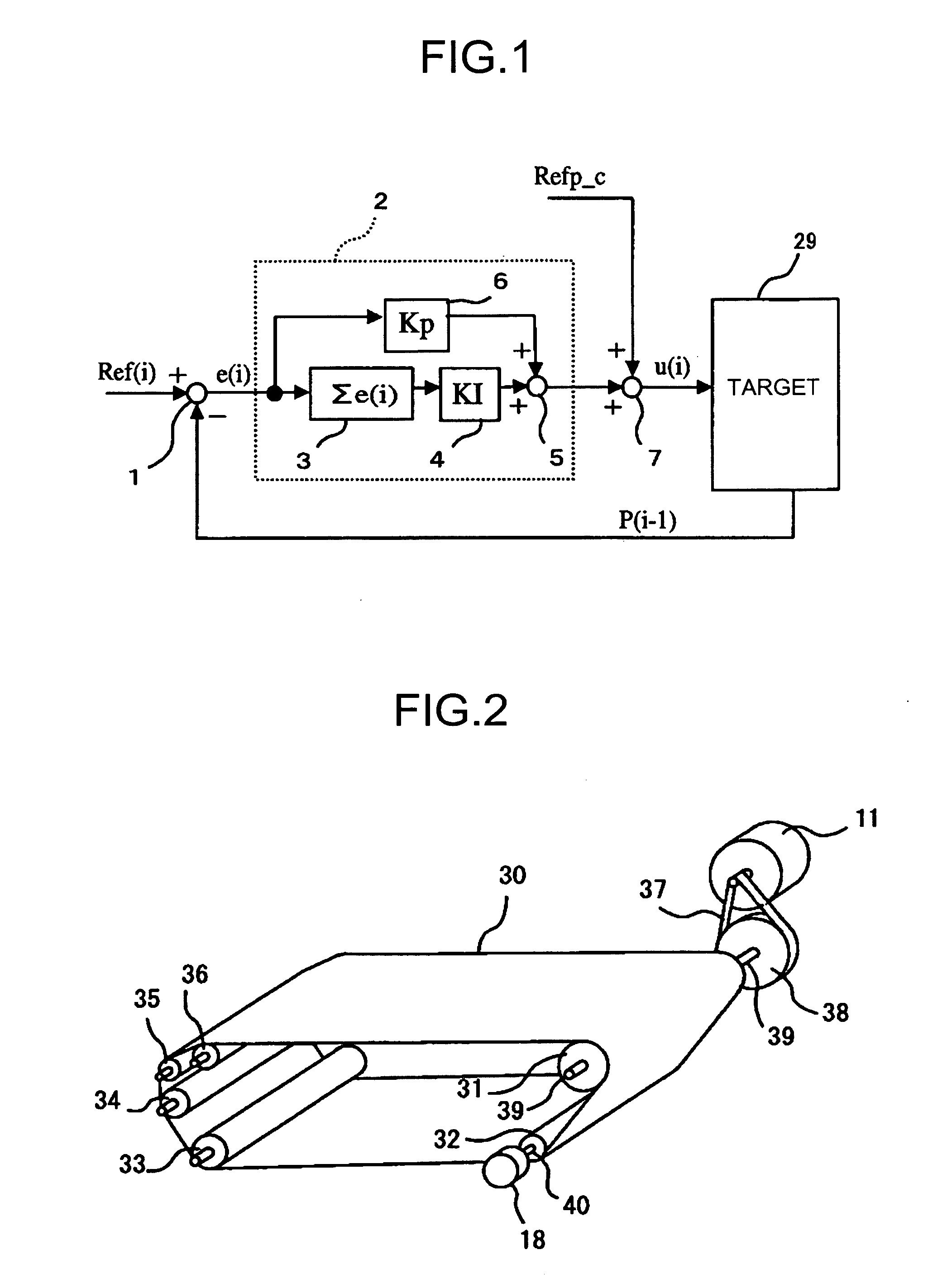
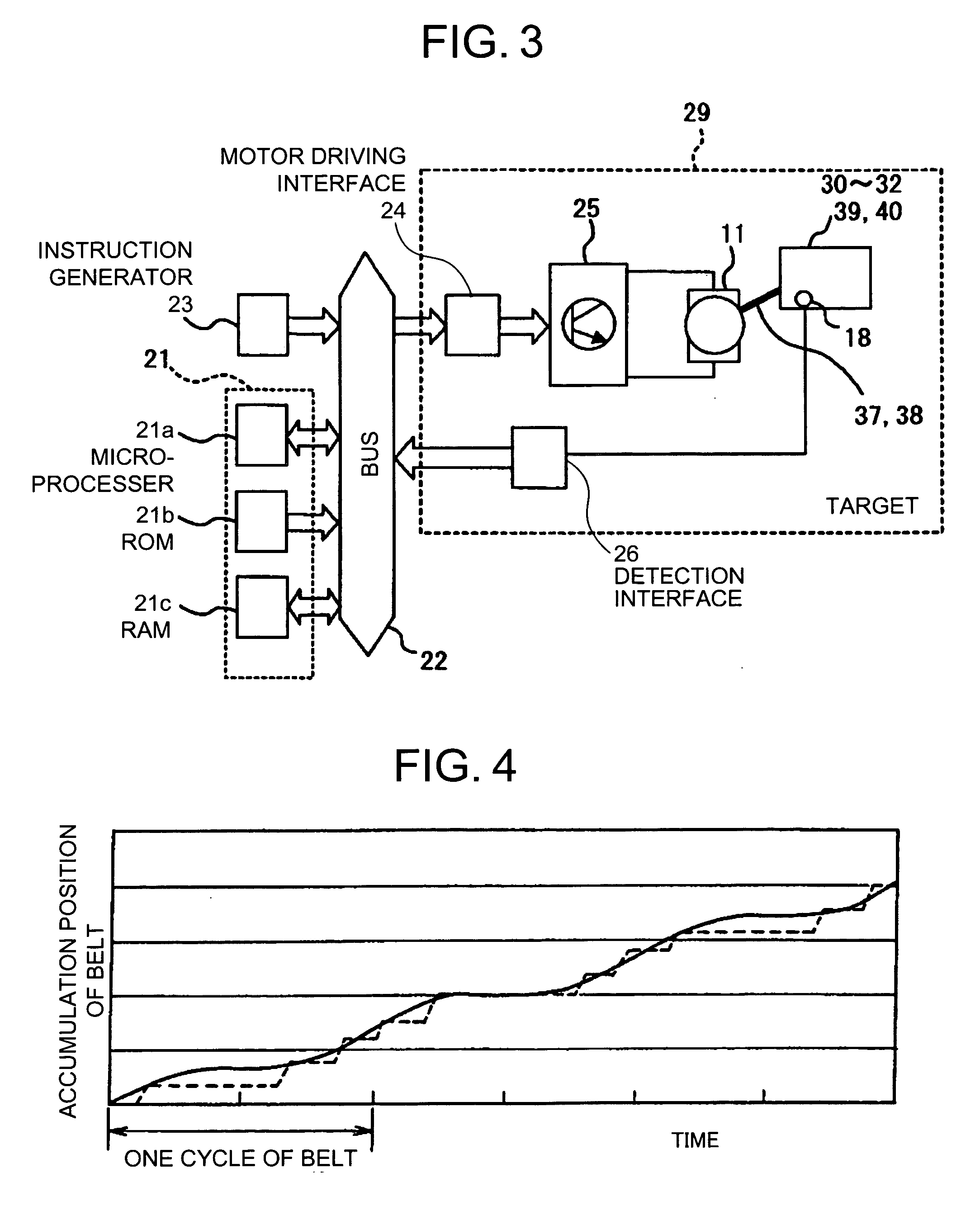
[0036]FIG. 3 is a block diagram of a hardware configuration of a control system for the pulse motor 11 and a controlling target thereof according to the The control system is a control system that digitally controls an angular displacement of the pulse motor 11 based on an output signal from the encoder 18.

[0037] The control system includes a microcomputer 21, a bus 22, an instruction generator 23, a motor driving interface 24, a motor driving apparatus 25 serving as a motor driving unit, and a detection interface 26.

[0038] The microcomputer 21 includes a microprocessor 21a, a read only memory (ROM) 21b, a random access memory (RAM) 21c, and the like. The microprocessor 21a, the ROM 21b, the RAM 21c and the like are connected to one another via the bus 22, respectively.

[0039] The instruction generator 23 outputs an instruction signal instructing a drive frequency of a driving pulse signal to the pulse motor 11. An output of the instruction generator 23 is also connected to the bu...

third embodiment

[0064] A third embodiment where the present invention is applied to a color copying machine is explained next with reference to the accompanying drawings.

[0065]FIG. 9 is a schematic configuration view of a color copying machine according to the third embodiment. In FIG. 9, an apparatus main unit 110 of the color copying machine includes a drum-like photoconductor (hereinafter, “photosensitive drum”) 112 serving as image carrier slightly near to the left side from a center inside an exterior case 111. Around the photosensitive drum 112, a charger 113 disposed above the photosensitive drum 112, a rotary developing device 114 serving as a developing unit, an intermediate transfer unit 115, a cleaning device 116, an electricity remover 117, and the like are arranged along a rotating direction indicated by arrow (counterclockwise) in this order.

[0066] A light writing device serving as an exposing unit, for example, a laser writing device 118 is disposed above the charger 113, the rotary...

fourth embodiment

[0079] A fourth embodiment where the present invention is applied to a color copying machine is explained next with reference to the accompanying drawings.

[0080]FIG. 10 is a schematic configuration diagram of a color copying machine according to the fourth embodiment. In FIG. 10, a photosensitive belt 201 serving as a latent image carrier is an endless photosensitive belt where a photosensitive layer such as organic photo semiconductor (OPC) is formed in a thin film on an outer peripheral face of a closed-loop belt base member made of nylon (NL). The photosensitive belt 201 is supported by three photoconductor conveying rollers 202 to 204 serving as supporting and rotating members and is rotationally moved in a direction of arrow A by a driving motor (not shown).

[0081] A charger 205, an exposure optical system (hereinafter, “LSU”) 206 as an exposing unit, developing elements 207 to 210 corresponding to respective colors of black, yellow, magenta, and cyan, an intermediate transfer ...


PUM


Abstract

An endless belt is spanned around at least one driving member and at least one supporting member. The driving member is driven by a pulse motor. An angular displacement of the driving member is detected, a difference between detected angular displacement and a target angular displacement is calculated, a frequency of a driving pulse used to drive the pulse motor is calculated based on the difference and a reference driving pulse frequency, and the pulse motor is controlled based on a driving pulse with calculated frequency. The target angular displacement is set so as to cancel a specific velocity fluctuation component of a surface velocity of the belt produced when the drive member is rotated at a constant angular velocity and that is smaller than amount of surface movement of the belt in one driving pulse.

Description

CROSS-REFERENCE TO RELATED APPLICATIONS [0001] The present document incorporates by reference the entire contents of Japanese priority document, 2004-367129 filed in Japan on Dec. 20, 2004. BACKGROUND OF THE INVENTION [0002] 1. Field of the Invention [0003] The present invention generally relates to a technology for controlling driving of an endless belt, and more specifically relates to controlling driving of an endless belt in an image forming apparatus. [0004] 2. Description of the Related Art [0005] An endless belt spanned around rotating or non-rotating members is used in image forming apparatuses. To maintain the velocity of such a belt constant, a target velocity of the belt is set and the velocity of the belt is maintain at the target velocity based on a feedback control using the real velocity of the belt. [0006] For example, Japanese Patent Application Laid-open No. 2004-187413 discloses to perform a feedback control on a pulse motor such that a belt, which is spanned arou...

Claims


Application Information

Patent Timeline
Patent Type & Authority Applications(United States)
IPC IPC(8): G03G15/00
CPCG03G15/50G03G2215/00139G03G2215/0119G03G2215/0158G03G2215/1623
Inventor ANDOH, TOSHIYUKIMATSUDA, HIROMICHIYOKOKAWA, NOBUTOIMAI, RYOJIMATSUDA, YUJIOKAMURA, HIROSHIKOBAYASHI, KAZUHIKOMIURA, YOHEIYOKOYAMA, MASATO
Owner RICOH KK
Why Eureka
Try Eureka