
High-strength four-phase steel alloys

Active Publication Date: 2006-06-29
CMC STEEL FABTORS
View PDF9 Cites 24 Cited by
  • Summary
  • Abstract
  • Description
  • Claims
  • Application Information

AI Technical Summary

Benefits of technology

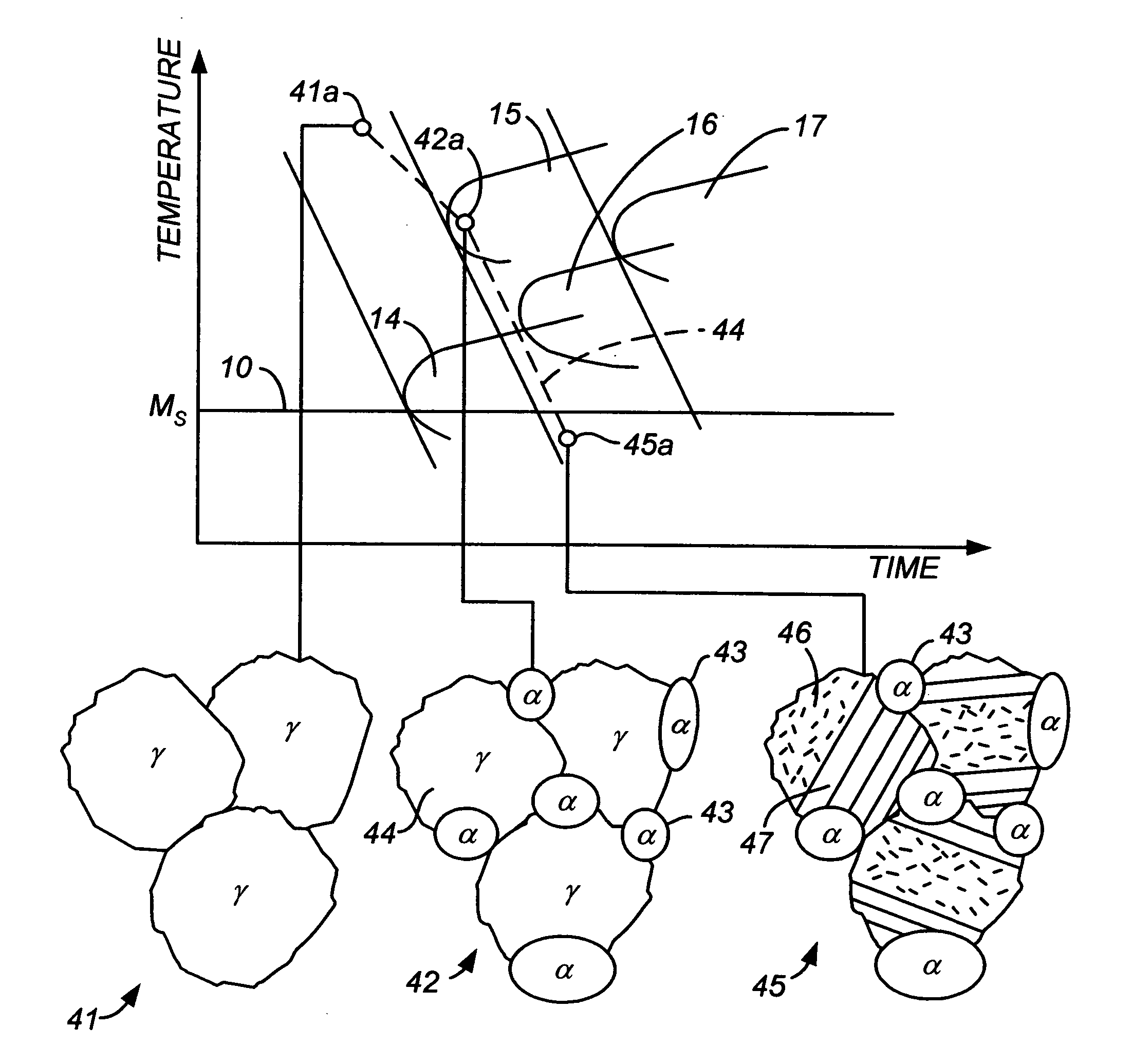
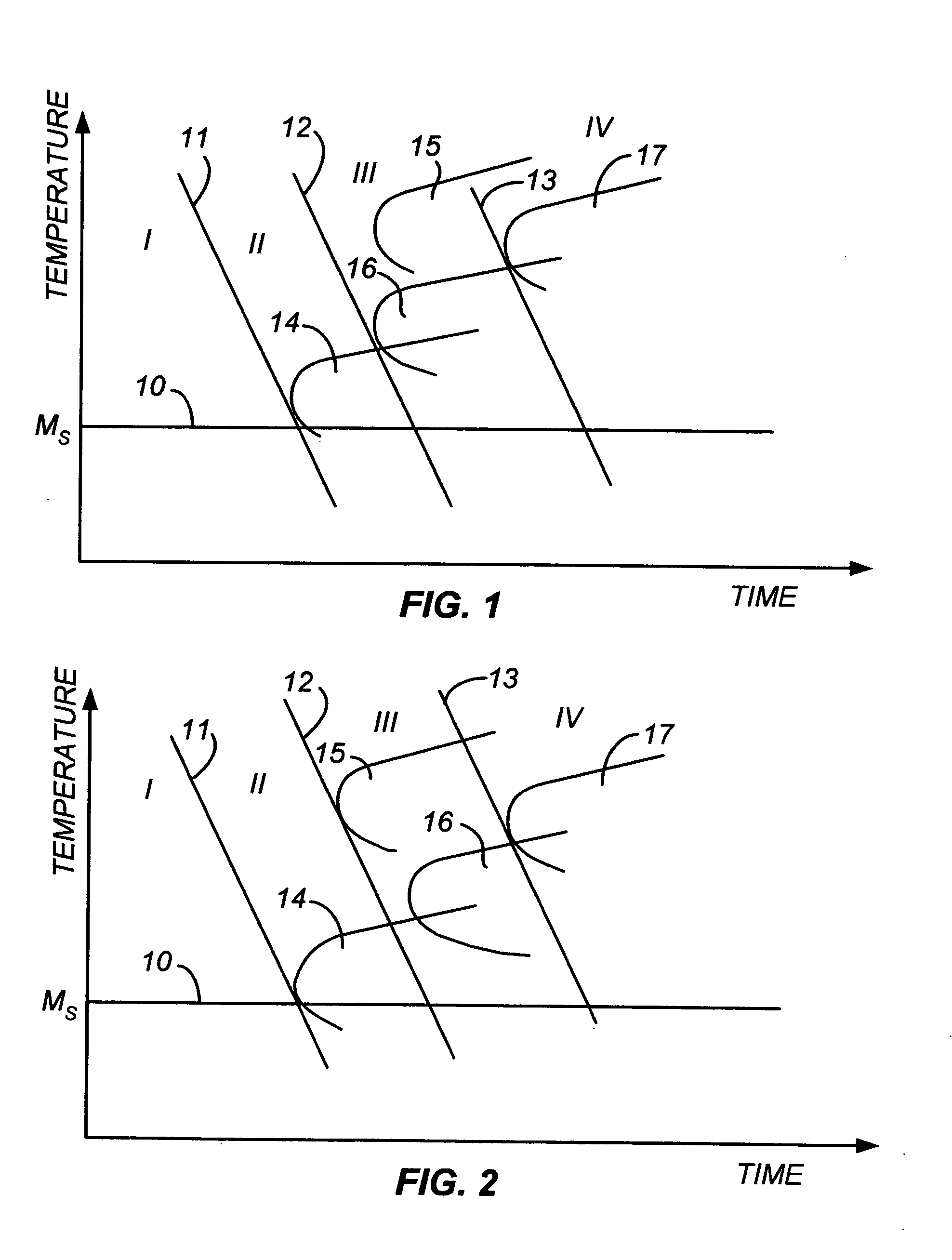
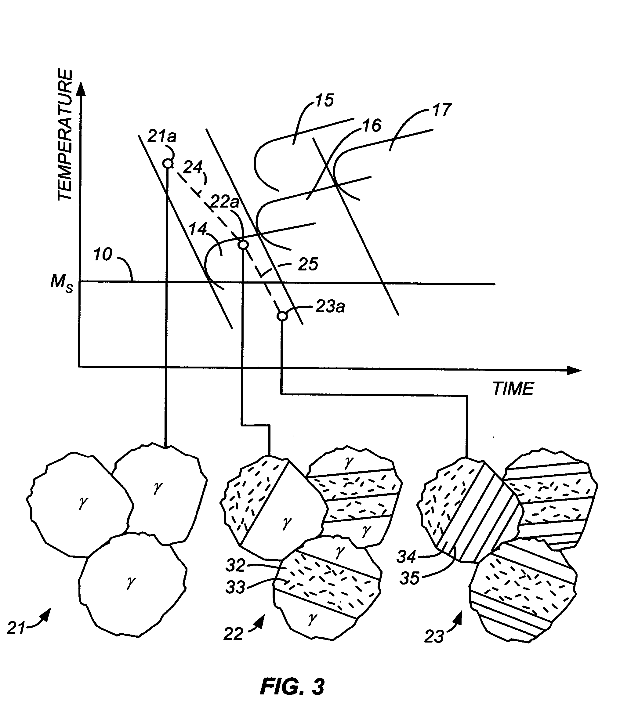
[0018] It has now been discovered that strong, ductile, corrosion-resistant carbon steels and alloy steels with a reduced risk of failure due to carbide precipitates are manufactured by a process that includes the formation of a combination of ferrite regions and martensite-austenite lath regions (regions containing laths of martensite alternating with thin films of austenite), with nucleation sites within the ferrite regions for carbide precipitation. The nucleation sites direct the carbide precipitation to the interiors of the ferrite regions and thereby disfavor precipitation at phase or grain boundaries. The process begins with the formation of a substantially martensite-free austenite phase or a combination of martensite-free austenite and ferrite as separate phases. The process then proceeds with cooling of the austenite phase to convert a portion of the austenite to ferrite while allowing carbides to precipitate in the bulk of the newly formed ferrite. This newly formed ferrite phase which contains small carbide precipitates at sites other than the phase boundaries is termed “lower bainite.” The resulting combined phases (austenite, lower bainite, and in some cases ferrite) are then cooled to a temperature below the martensite start temperature to transform the austenite phase to a lath structure of martensite and austenite. The final result is therefore a microstructure that contains a combination of the lath structure and lower bainite, or a combination of the lath structure, lower bainite, and (carbide-free) ferrite, and can be achieved either by continuous cooling or by cooling combined with heat treatments. The carbide precipitates formed during the formation of the lower bainite protect the microstructure from undesired carbide precipitation at phase boundaries and grain boundaries during subsequent cooling and any further thermal processing. This invention resides both in the process and in the multi-phase alloys produced by the process. Analogous effects will result from allowing nitrides, carbonitrides, and other precipitates to form in the bulk of the ferrite region where they will serve as nucleation sites that will prevent precipitation of further amounts of these species at the phase and grain boundaries.

Problems solved by technology

In certain alloys the carbides produced by autotempering add to the toughness of the steel while in others the carbides limit the toughness.
Another factor affecting the strength and toughness of the steel is the presence of dissolved gases.
Hydrogen gas in particular is known to cause embrittlement as well as a reduction in ductility and load-bearing capacity.
Cracking and catastrophic brittle failures have been known to occur at stresses below the yield stress of the steel, particularly in line-pipe steels and structural steels.
In certain applications, such as steels produced in mini-mills, operations involving electric arc furnaces, and operations involving ladle metallurgy stations, vacuum degassing of molten steel is not economical, and either a limited vacuum or no vacuum is used.
This removes the dissolved hydrogen, but unfortunately it also causes carbide precipitation.
In many cases, carbide precipitation is very difficult to avoid, particularly since the formation of multi-phase steel necessarily involves phase transformations by heating or cooling, and the saturation level of carbon in a particular phase varies from one phase to the next.
Thus, low ductility and susceptibility to corrosion are often problems that are not readily controllable.

Method used


Image

  • High-strength four-phase steel alloys
  • High-strength four-phase steel alloys
  • High-strength four-phase steel alloys

Examples


example 1

[0048] For a steel alloy containing 9% chromium, 1% manganese, and 0.08% carbon, cooling from the austenitic phase at a rate faster than about 5° C. / sec will result in a martensite-austenite lath microstructure that contains no carbide precipitates. If a slower cooling rate is used, namely one within the range of about 1° / sec to about 0.15° C. / sec, the resulting steel will have a microstructure containing regions of martensite laths alternating with thin films of austenite as well as lower bainite regions (ferrite grains with small carbide precipitates within the ferrite) but no carbide precipitates at the phase interfaces, and will therefore be within the scope of the present invention. If the cooling rate is lowered further to below about 0.1° C. / sec, the resulting microstructure will contain fine pearlite (troostite) with carbide precipitates at the phase boundaries. Small amounts of these precipitates can be tolerated, but in preferred embodiments of this invention, their presen...

example 2

[0050] For a steel alloy containing 4% chromium, 0.5% manganese, and 0.08% carbon, cooling from the austenitic phase at a rate faster than about 100° C. / sec will result in a martensite-austenite lath microstructure that contains no carbide precipitates. If a slower cooling rate is used, namely one that is less than 100° C. / sec but higher than 5° C. / sec, the resulting steel will have a microstructure containing regions of martensite laths alternating with thin films of austenite as well as lower bainite regions (ferrite grains with small carbide precipitates within the ferrite) but no carbide precipitates at the phase interfaces, and will therefore be within the scope of the present invention. If the cooling rate is lowered further to a range of 5° C. / sec to 0.2° C. / sec, the resulting microstructure will contain upper bainite with carbide precipitates at the phase boundaries, thereby falling outside the scope of this invention. This can be avoided by using a slow cooling rate followe...


PUM

PropertyMeasurementUnit
Temperatureaaaaaaaaaa
Lengthaaaaaaaaaa

Abstract

A carbon steel alloy that exhibits the combined properties of high strength, ductility, and corrosion resistance is one whose microstructure contains ferrite regions combined with martensite-austenite regions, with carbide precipitates dispersed in the ferrite regions but without carbide precipitates are any of the interfaces between different phases. The microstructure thus contains of four distinct phases: (1) martensite laths separated by (2) thin films of retained austenite, plus (3) ferrite regions containing (4) carbide precipitates. In certain embodiments, the microstructure further contains carbide-free ferrite regions.

Description

BACKGROUND OF THE INVENTION [0001] 1. Field of the Invention [0002] This invention resides in the field of steel alloys, particularly those of high strength, toughness, corrosion resistance, and ductility, and also in the technology of the processing of steel alloys to form microstructures that provide the steel with particular physical and chemical properties. [0003] 2. Description of the Prior Art [0004] Steel alloys of high strength and toughness whose microstructures are composites of martensite and austenite phases are disclosed in the following United States patents and published international patent application, each of which is incorporated herein by reference in its entirety: [0005] U.S. Pat. No. 4,170,497 (Gareth Thomas and Bangaru V. N. Rao), issued Oct. 9, 1979 on an application filed Aug. 24, 1977 [0006] U.S. Pat. No. 4,170,499 (Gareth Thomas and Bangaru V. N. Rao), issued Oct. 9, 1979 on an application filed Sep. 14, 1978 as a continuation-in-part of the above applicat...

Claims


Application Information

Patent Timeline
IPC IPC(8): C22C38/18C21D6/00
CPCC21D1/18C21D6/002C21D8/005C21D2211/008C21D2211/003C21D2211/005C21D2211/001C21D6/00
Inventor KUSINSKI, GRZEGORZ J.THOMAS, GARETH
Owner CMC STEEL FABTORS
Learn More