Hammer mechanism for power tool

Inactive Publication Date: 2006-06-29
BLACK & DECKER INC
View PDF31 Cites 8 Cited by
  • Summary
  • Abstract
  • Description
  • Claims
  • Application Information

AI Technical Summary

Benefits of technology

[0021] This provides the advantage of a more compact con

Problems solved by technology

The reciprocation of the hollow piston causes the ram member to move with the piston and cause compression of the air in the piston, which in turn causes the ram to impart impacts on an end of the tool bit, thus causing the hammering action of the power tool.
EP0775556 suffers from the drawback that a

Method used


Image

  • Hammer mechanism for power tool
  • Hammer mechanism for power tool
  • Hammer mechanism for power tool

Examples


Embodiment Construction

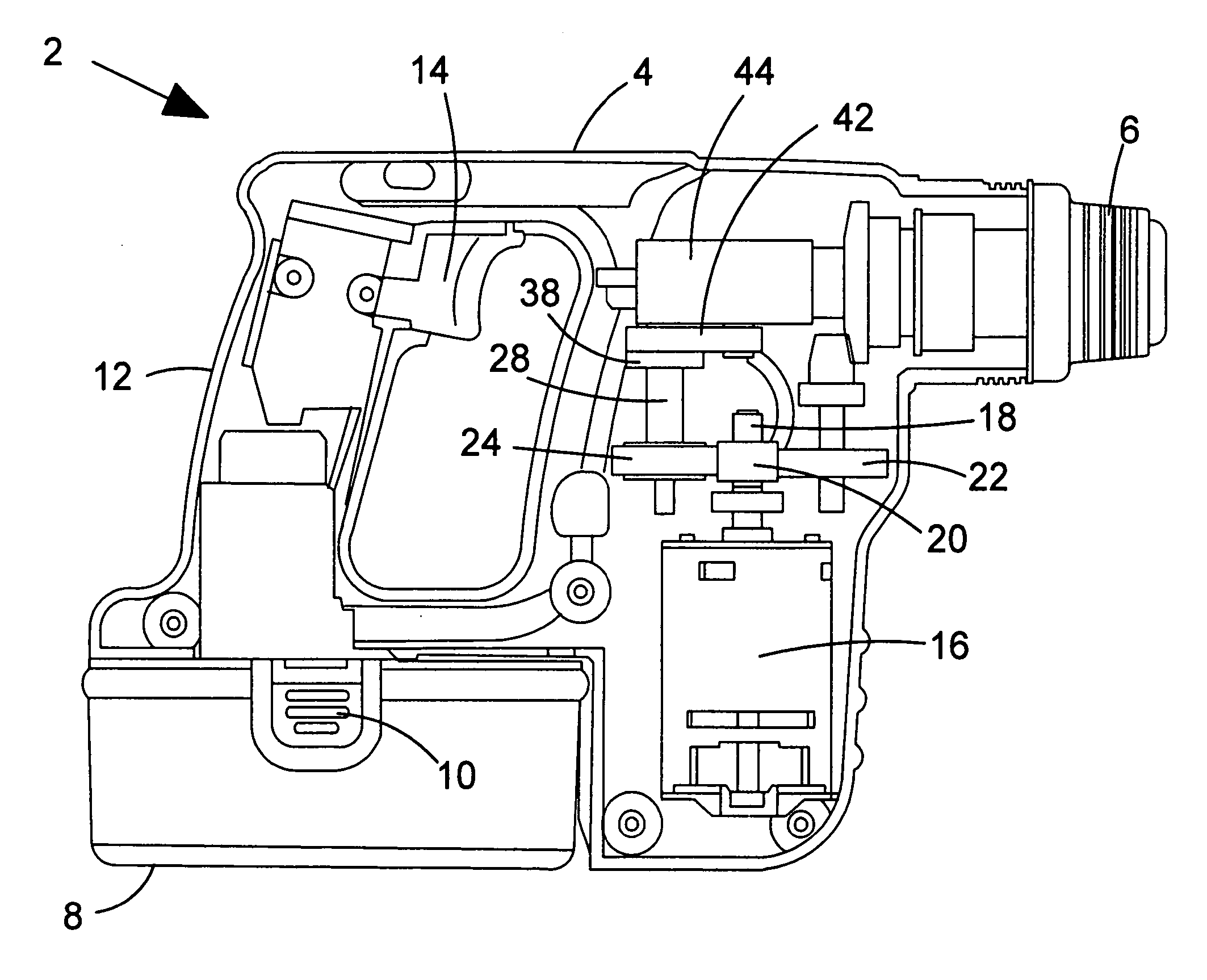
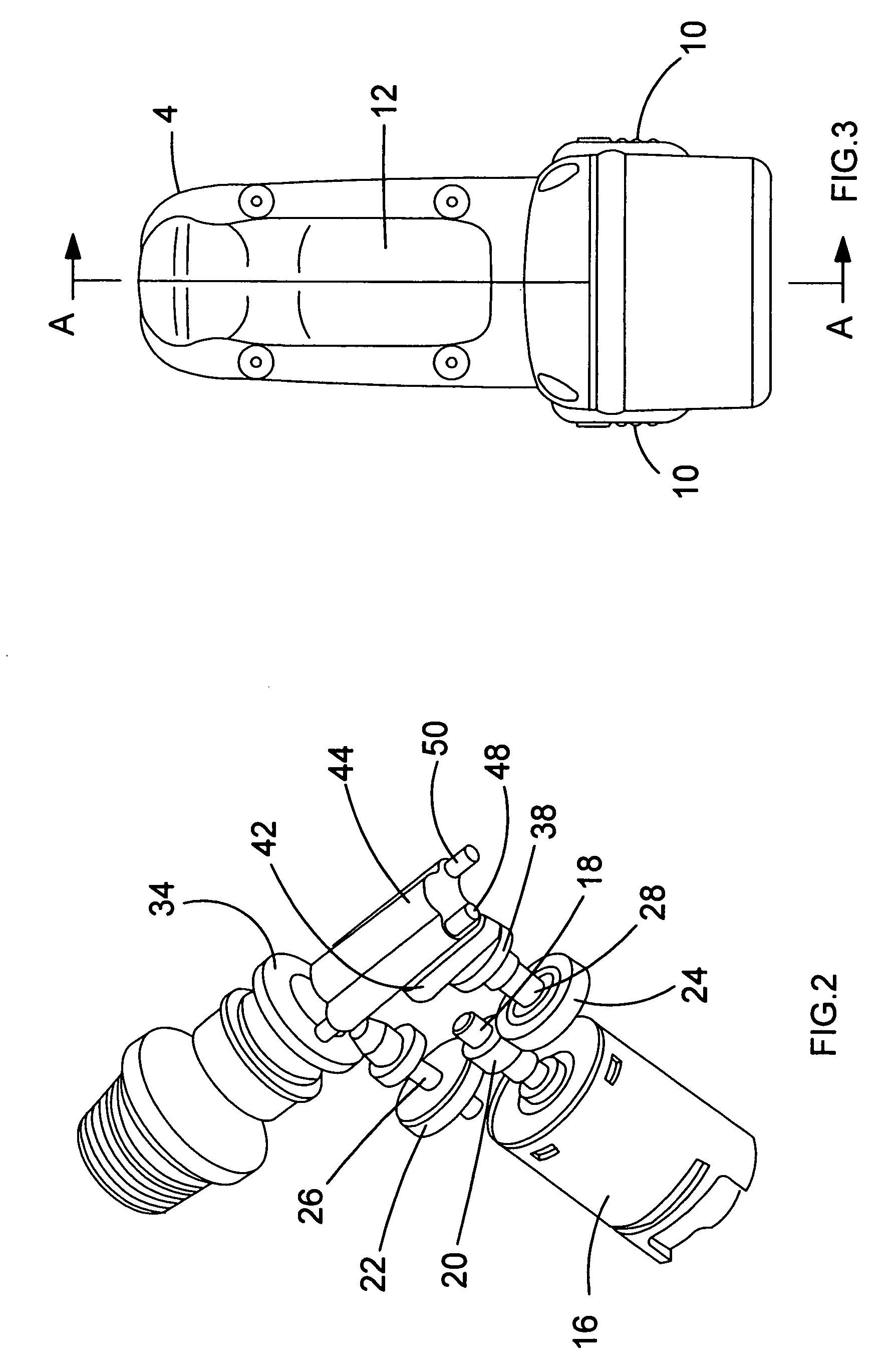
[0031] Referring to FIG. 1, a hammer drill shown generally by 2 comprises a housing 4 formed from two clam shell halves of durable plastics material, as will be understood by persons skilled in the art. Extending from a forward end of housing 4 is a chuck 6 or similar device for gripping a tool bit. A rechargeable battery pack 8 is removably attached to the bottom of the housing, and can be removed from the housing 4 by depressing clips 10 to release the battery pack for recharging. The housing 4 comprises a handle portion 12 having a trigger 14 for activation of the hammer drill by means of an electric motor 16 disposed in the housing. An output shaft 18 extends from the electric motor 16, the output shaft 18 having a pinion 20 formed thereon. The pinion 20 has a plurality of gear teeth formed on its outer surface (not shown).

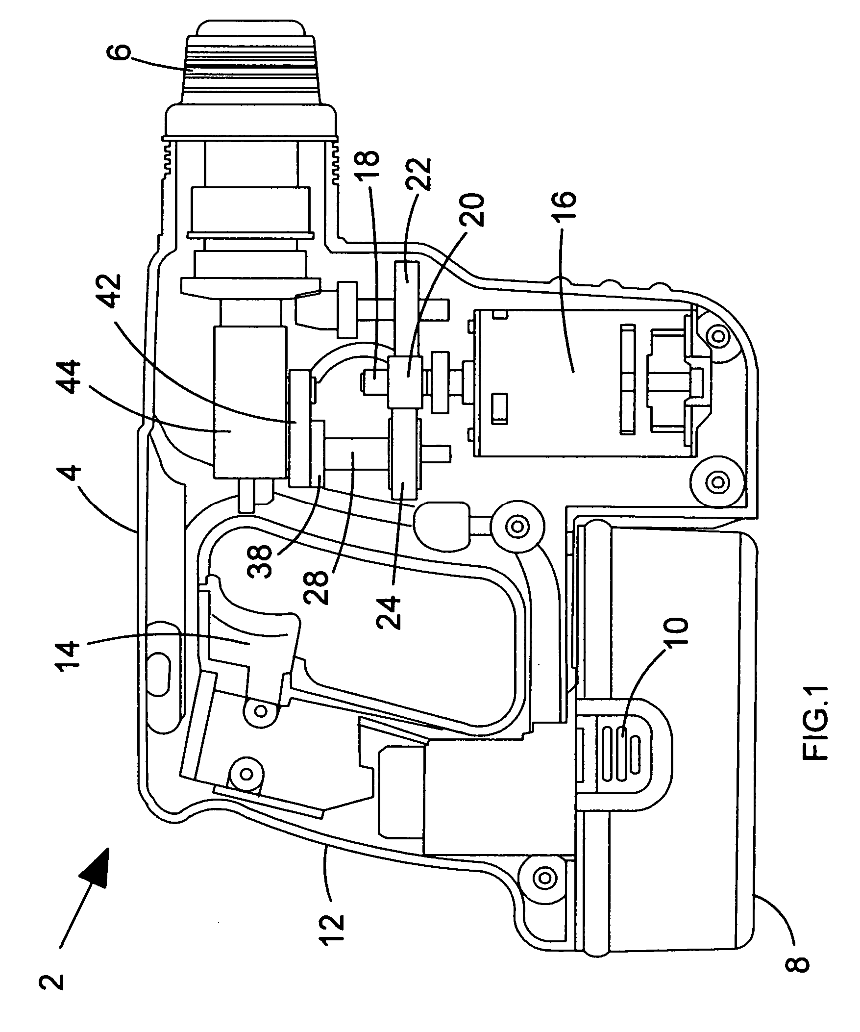
[0032] Referring to FIGS. 1, 2 and 4, pinion 20 of output shaft 18 intermeshes with a first gear 22 and a second gear 24. As a result, when output shaft 18 i...


PUM


Abstract

A rotary hammer includes a motor with an output shaft and pinion. The pinion drives a gear which is mounted to a drive shaft. A crank plate having an eccentrically disposed crank pin is mounted to the top of the drive shaft. A crank arm is pivotally connected to the crank pin and to the underside of a hollow piston. Hollow piston defines an internal bore, and the hollow piston is slidably mounted on two guide rods. Rotation of the drive shaft and turns the crank plate, and the eccentric motion of crank pin drives the crank arm. Due to the pivotal connection between the crank arm and the hollow piston 44, the hollow piston is caused to reciprocate back and forth along the guide rods.

Description

FIELD OF THE INVENTION [0001] The present invention relates to a hammer mechanism for a power tool, and to a power tool incorporating such a mechanism. The invention relates particularly, but not exclusively to a hammer mechanism for a hammer drill having a hammer mode, a rotary mode, and a combined hammer and rotary mode, and to a power tool incorporating such a mechanism. BACKGROUND OF THE INVENTION [0002] Hammer drills are power tools, which can generally operate in one of three modes of operation. Generally, a hammer drill will have a tool bit, which can be operated in a hammering mode, a drilling mode and a combined hammering and drilling mode. [0003] European patent application EP0775556 describes a drive mechanism for such a hammer drill. This mechanism comprises a hollow piston in which a ram member is slidably disposed. The hollow piston is slidably mounted on a pair of guide rods and connected at the rear of the hollow piston to a wobble plate such that the hollow piston c...

Claims


Application Information

Patent Timeline
IPC IPC(8): B25D9/00
CPCB25D11/125B25D16/00B25D17/06B25D2211/003B25D2217/0019B25D2250/235B25D2250/331
Inventor HANKE, ANDREAS
Owner BLACK & DECKER INC
Why Eureka
Try Eureka