Side-scattering light guides

a light guide and side-scattering technology, applied in the direction of instruments, cladded optical fibres, mechanical instruments, etc., can solve the problems of difficult control of the process of producing such a light guide, unsatisfactory overall impression, and bright edges of the guide much brighter than the centre, so as to reduce the available illuminating length, minimize backscattering, and reduce the effect of absorption

Inactive Publication Date: 2006-06-29
POLY OPTICS AUSTRALIA
View PDF16 Cites 51 Cited by
  • Summary
  • Abstract
  • Description
  • Claims
  • Application Information

AI Technical Summary

Benefits of technology

[0016] The diffusing jacket may surround part of the core, for instance half the core. The diffusing jacket may be a transmitting diffuser, and it may be formed from a translucent material including one of the translucent grades of polyethylene, PMMA, PTFEPTFE, ABS, PVC or glass. Alternatively, the diffusing jacket may be a transmitting diffuser that is formed from a transparent material with one or more non-smooth surfaces. The surface relief may include roughness, an imposed pattern or other deviations from smoothness. Suitable materials include one of the transparent grades of PMMA, PTFE, ABS, PVC or glass. Alternatively, the diffusing jacket may be a transmitting diffuser, and it may feature one or more non-smooth surface(s) of a translucent material. Alternatively again, the diffuser jacket may be opaque and reflective. Alternatively again, the diffuser jacket may act as both a transmitting diffuser and a reflective diffuser. It may be apertured. Parts of the jacket may be translucent, other parts may be translucent with a degree of diffuse reflectance and other parts may be opaque and diffusely reflective. Preferably, the diffuser jacket has low absorption.
[0017] Placing the diffuser jacket external to the low refractive index sheath minimizes backscattering and retains a key advantage of the diffuser particles. Diffusing elements which are in intimate contact with the core usually reduce available illuminating lengths and also may induce backscattering and hence reduce the fraction of light incident on the fibre that can be side-emitted. An opaque and reflective jacket may be apertured, and the apertures may be surrounded by a transmitting diffuser. The aperture may be a longitudinal slit.

Problems solved by technology

Although the scattered light has a more aesthetically pleasing appearance, the process of producing such a light guide is particularly difficult to control.
An additional problem is that when viewed from the side, the edges of the guide appear to be much brighter than the centre.
Many observers perceive the brightness as less than an objective measure would indicate, and the overall impression is aesthetically unsatisfactory.
A further problem is that side-scattered light tends to be emitted in a radially symmetric fashion and a substantial fraction of it may be in unwanted directions.
An additional problem is that for some types of diffuser particles the fraction of light scattered out per metre of fibre varies with the light's wavelength.
Colour variation of side-emitted light along a light guide, particularly one using white light, is unacceptable for many applications.

Method used


Image

  • Side-scattering light guides
  • Side-scattering light guides
  • Side-scattering light guides

Examples


Embodiment Construction

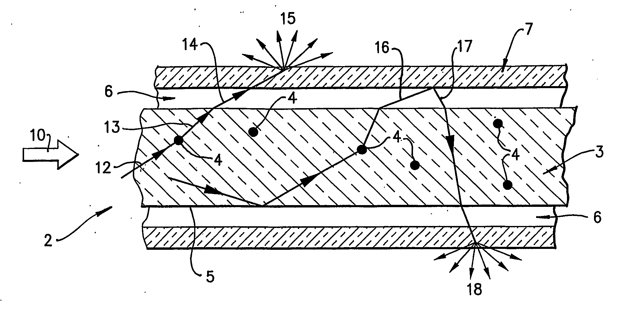
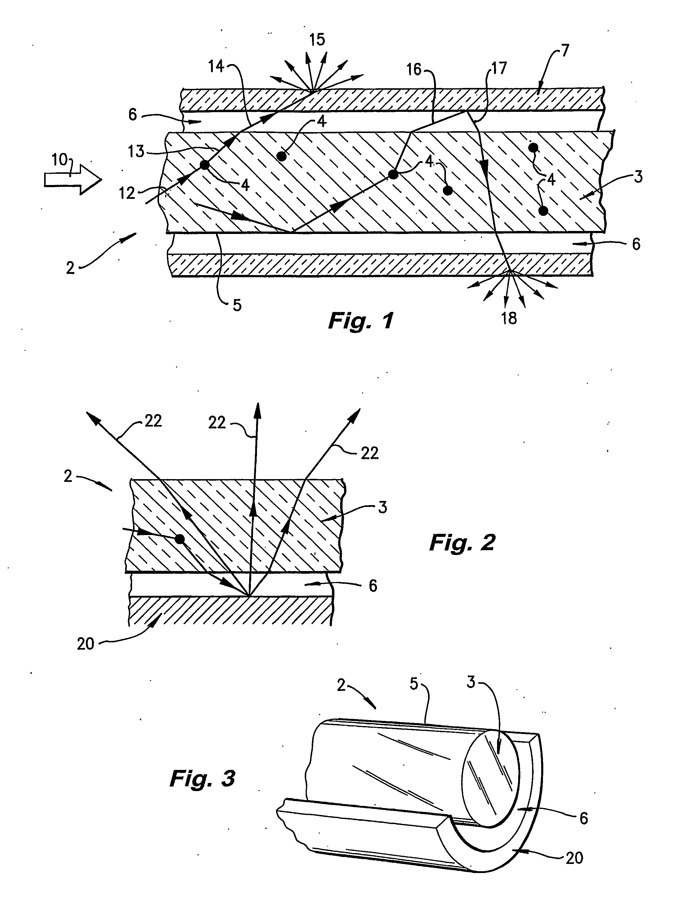
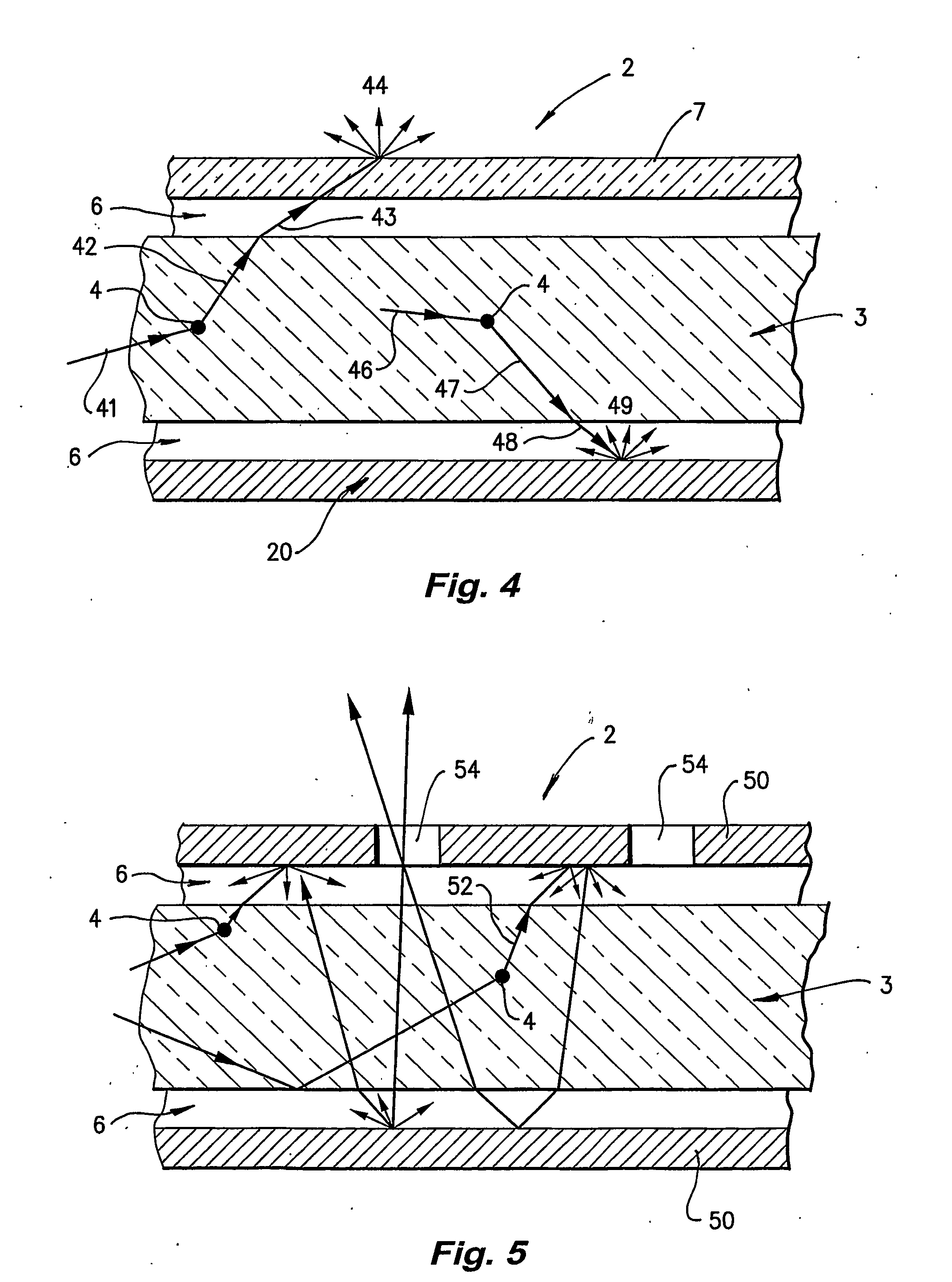
[0032] Referring first to FIG. 1, side-scattering light guide 2 comprises a core 3 seeded with diffuser particles 4. The external surface 5 of core 3 is totally surrounded by, and in contact with, a sheath of lower refractive index material 6. There is also a transmitting diffuser jacket 7.

[0033] Core 3 is a polymer formed from a polymer matrix such as Poly-methly methacrylate (PMMA) or a polymerised acrylate mixture consisting primarily of methyl methacrylate (MMA) and allyl diglycol carbonate (CR39). Alternatively, butyl methacrylate (BMA) may be substituted for MMA. In other examples core 3 may be made from polystyrene or glass.

[0034] The diffuser particles 4 are formed of a cross-linked polymer, which is capable of being added to the core matrix material without the diffuser particles 4 dissolving, melting or significantly deforming. In most cases the core is made by in situ polymerisation. Silica particles can be used with a glass core. The diffuser particles 4 must have a hi...


PUM


Abstract

The invention relates to side-scattering light guides that generally comprise a core of transparent optically homogenous material seeded with diffuser particles. The light guide also comprises an optically transmitting sheath, having a lowerrefractive index than the core, surrounding and in contact with the sides of the core to prevent any light being transmitted along the core from escaping through the core's sides. In general, the diffuser particles impart only a small deviation to light rays incident upon them, and are distributed to scatter light being transmitted along the core so that at least some of the scattered light exits the sides of the core. A diffusing jacket is arranged to intercept scattered light exiting the sides of the core.

Description

FIELD OF THE INVENTION [0001] The invention relates to side-scattering light guides that comprise a core of transparent optically homogenous material seeded with diffuser particles. In general, the diffuser particles impart only a small deviation to light rays incident upon them, and are distributed to scatter light being transmitted along the core so that at least some of the scattered light exits the sides of the core. BACKGROUND ART [0002] One type of side-scattering light guide is described in U.S. Pat. No. 6,169,836 (Sugiyama). This patent describes a light guide formed with scattering particles dispersed in the core. The scattering particles have a significantly different refractive index from the core material and therefore cause relatively large scattering angles. The scattered light from this invention has an aesthetically unpleasing appearance. [0003] U.S. Pat. No. 5,542,017 (Koike) describes a side-scattering light guide that has a core containing an irregular structure o...

Claims


Application Information

Patent Timeline
Patent Type & Authority Applications(United States)
IPC IPC(8): G02B6/028G02B6/02G02B6/00F21V8/00G02B6/28
CPCG02B6/001G02B6/02033G02B6/2817
Inventor JOSEPH, EDMOND KENNETHFRANKLIN, JAMES BRUCESMITH, GEOFFREY BURTON
Owner POLY OPTICS AUSTRALIA
Why Eureka
Try Eureka