Trochoid oil pump

a technology of oil pump and trochoid, which is applied in the direction of rotary/oscillating piston pump components, machines/engines, liquid fuel engines, etc., can solve the problems of difficult connection to adjacent contraction chambers, limited flat portion size, and clogging of gap

Active Publication Date: 2006-06-29
YAMADA SEISAKUSHO KK
View PDF10 Cites 8 Cited by
  • Summary
  • Abstract
  • Description
  • Claims
  • Application Information

AI Technical Summary

Problems solved by technology

This is because if the drive contact portions in the tooth surfaces of the external-tooth gear or internal-tooth gear are avoided, the size of the flat portions is very limited and the gap constituted by the flat portions also can be only within a limited range.
However, the size of the gap is not held, while enlarging in the rotation direction, correspondingly to the degree of volume reduction of th

Method used


Image

  • Trochoid oil pump
  • Trochoid oil pump
  • Trochoid oil pump

Examples


Embodiment Construction

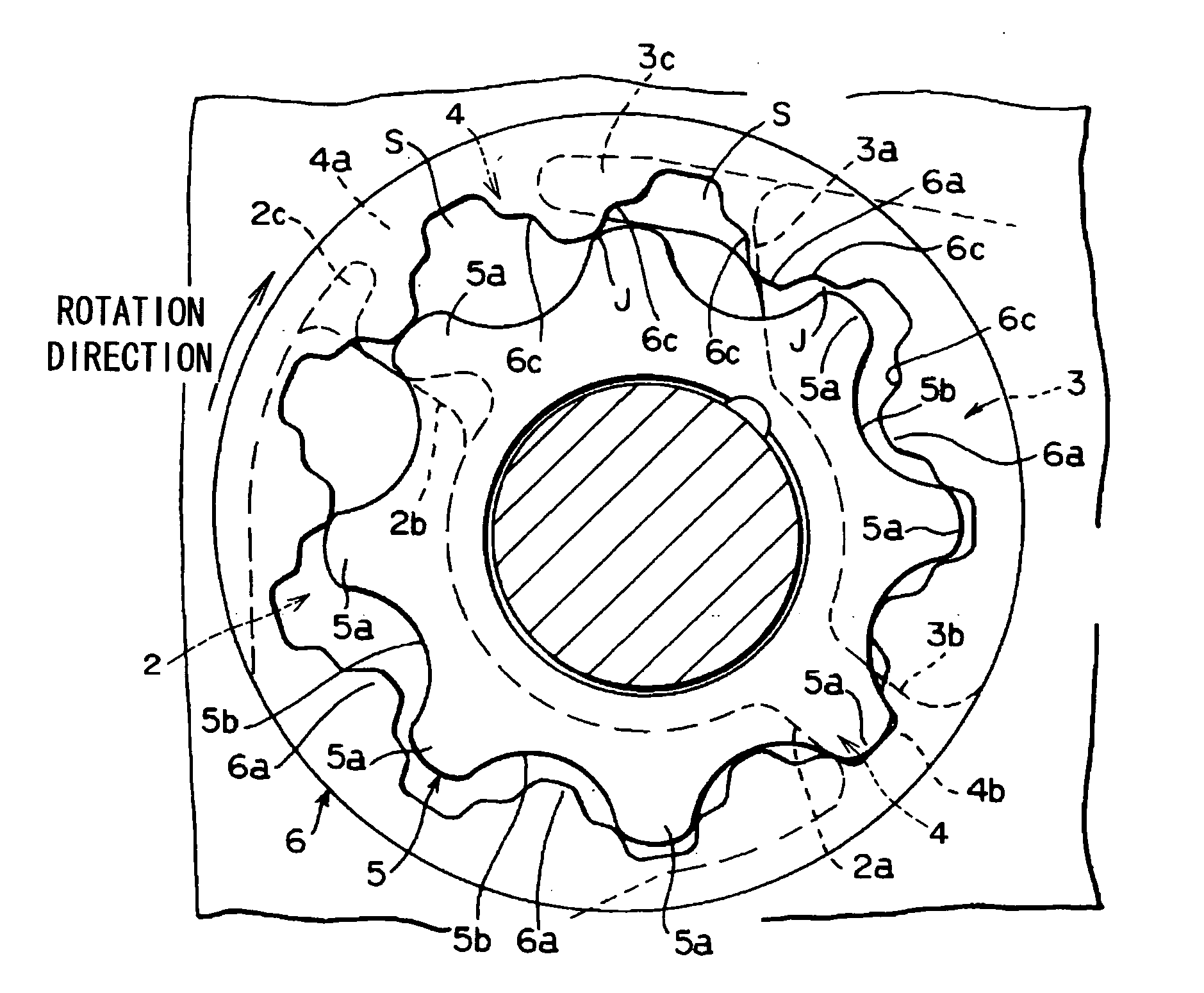
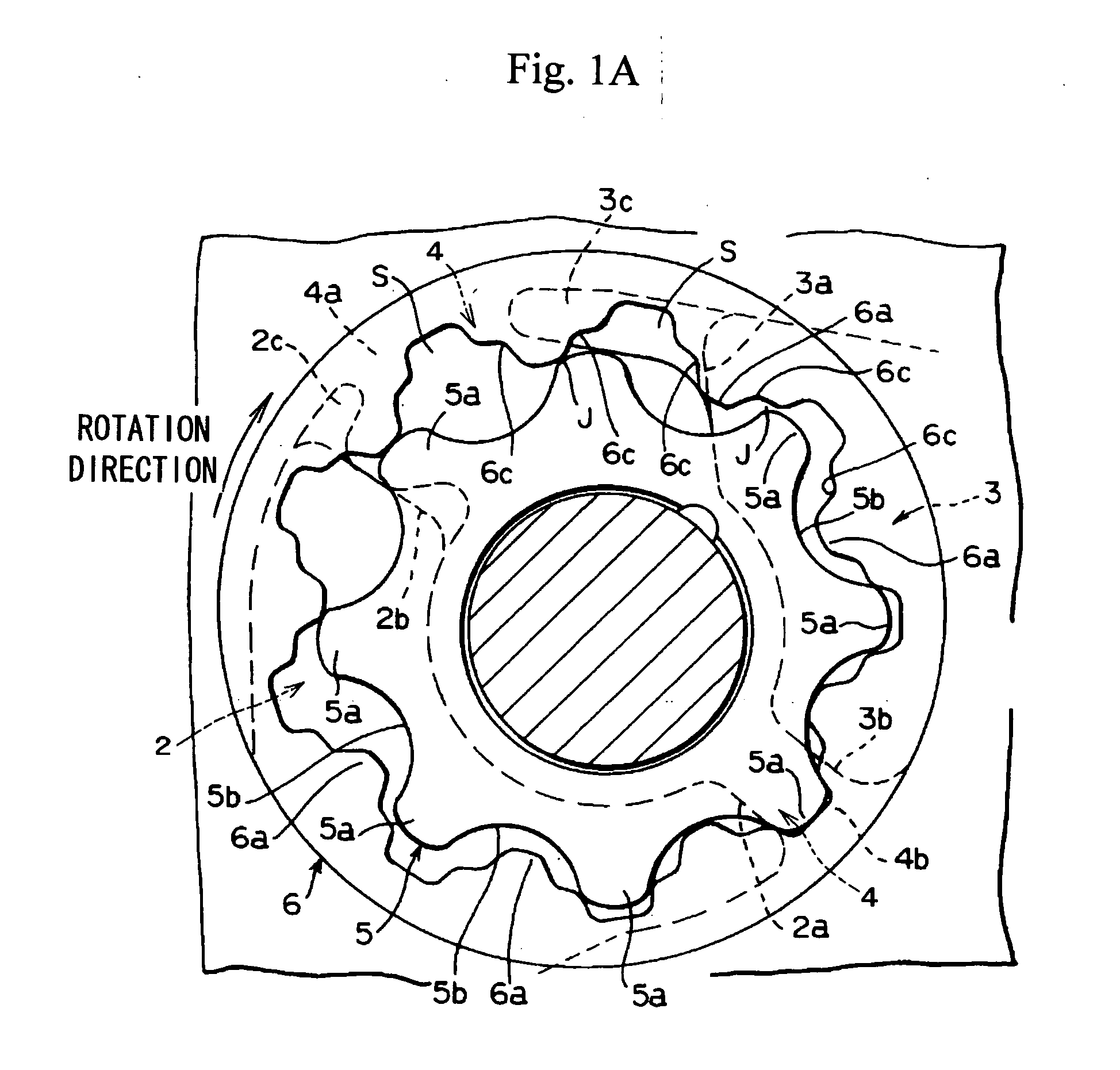
[0022] The best mode for carrying out the invention will be described below with reference to the drawings. In the trochoid pump in accordance with the present invention, as shown in FIG. 1(A), an inner rotor 5 and an outer rotor 6 with a trochoid tooth profile are provided inside a rotor chamber 1 formed inside a pump casing. In the rotor chamber 1, as shown in FIG. 1(A), an intake port 2 and a discharge port 3 are formed almost on the outer periphery along the circumferential direction of the chamber. More specifically, as shown in FIG. 1(A) and FIG. 4(A), the intake port 2 and discharge port 3 have a shape with a left-right asymmetry, and the intake port 2 is formed to have a region surface area larger than that of the discharge port 3.

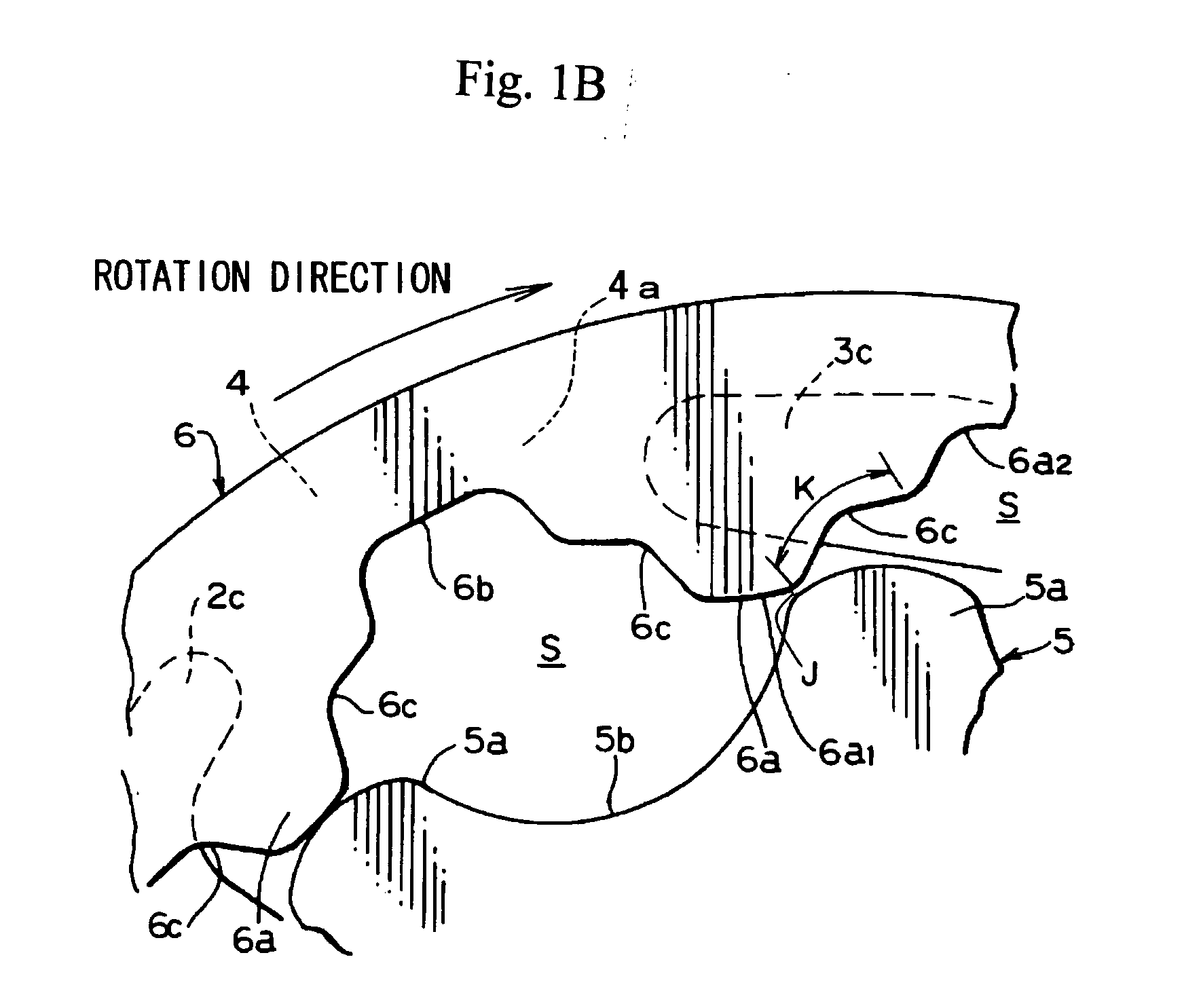
[0023] In the intake port 2, as shown in FIG. 1(A), an interdental space S formed by the rotation of the inner rotor 5 and outer rotor 6 moves, the end portion thereof that is first to reach the region of the intake port 2 becomes the leading end ...


PUM


Abstract

A trochoid oil pump, which enables the endurance to be increased and the reduction of discharge pulsations and noise to be achieved, and in which those results can be realized with a very simple structure. An interdental space constituted by an inner rotor and an outer rotor having trochoid tooth profile or substantially trochoid tooth profile starts a compression stroke in the location of a partition section between an intake port and a discharge portion, and a linking gap L is composed by the interdental space and a preceding adjacent interdental space realized in a discharge stroke. The linking gap expands gradually from the start of compression stroke to the discharge stroke.

Description

BACKGROUND OF THE INVENTION [0001] 1. Field of the Invention [0002] The present invention relates to a trochoid oil pump which enables the endurance to be increased and the reduction of discharge pulsations and noise to be achieved and in which those results can be realized with a very simple structure. [0003] 2. Description of the Related Art [0004] Japanese Patent Application Laid-open No. H5-215079 discloses that the space between adjacent contraction chambers and the space between the contraction chamber and a discharge chamber are throttled and a gap capable of linking the chambers is formed between the opposing tooth surfaces in which part of the tooth surface on the rear side in the rotation direction of each tooth of the external-tooth gear or part of the tooth surface on the forward side in the rotation direction of each tooth of the internal-contact gear of an internal-contact gear pump is receded over the entire tooth width. [0005] The technological contents disclosed in ...

Claims


Application Information

Patent Timeline
IPC IPC(8): F16N13/20F01C1/02F04C2/00F01C1/063
CPCF04C2/084F04C2/102F04C15/0007
Inventor ENZAKA, KAZUOKASAHARA, MASAHIROONO, YASUNORIFUJIKI, KENICHIKAI, KEIICHISENGA, YOSHIAKIKANEKO, ATSUSHI
Owner YAMADA SEISAKUSHO KK
Why Eureka
Try Eureka