Fuel cell and method for manufacturing electrolyte membrane for fuel cell

Inactive Publication Date: 2006-06-29
TOYOTA JIDOSHA KK
View PDF6 Cites 13 Cited by
  • Summary
  • Abstract
  • Description
  • Claims
  • Application Information

AI Technical Summary

Problems solved by technology

In fuel cells of solid oxide type, while it is possible to reduce the membrane resistance by reducing the thickness of the electrolyte membrane, it is extremely difficult in practice to form a fine thin membrane on the electrodes, which are formed form porous material, so that it is not possible to achieve a sufficiently thin film.
Where the electrolyte membrane is formed of a composite material comprising a hydrogen-permeable metal layer and an electrolyte layer in this way, th

Method used


Image

  • Fuel cell and method for manufacturing electrolyte membrane for fuel cell
  • Fuel cell and method for manufacturing electrolyte membrane for fuel cell
  • Fuel cell and method for manufacturing electrolyte membrane for fuel cell

Examples


embodiment 11

[0057]FIG. 24 is an illustration depicting the process of producing the electrolyte membrane of

[0058]FIG. 25A to FIG. 25D are illustrations depicting the separation preventing action of the groove.

[0059]FIG. 26A and FIG. 26B are plan views depicting two types of electrolyte membrane in Embodiment 11.

[0060]FIG. 27A and FIG. 27B are illustrations depicting the cross section of the electrolyte membrane of a Variation Example of Embodiment 11.

BEST MODE FOR CARRYING OUT THE INVENTION

[0061] The embodiments of the invention will be described in the following order. [0062] A. Embodiment 1 [0063] A1. Overall Composition [0064] A2. Electrolyte Membrane [0065] A3. Variation Example [0066] B. Embodiment 2 [0067] C. Embodiment 3 [0068] D. Embodiment 4 [0069] E. Embodiment 5 [0070] F. Embodiment 6 [0071] G. Embodiment 7 [0072] H. Embodiment 8 [0073] I. Embodiment 9 [0074] J. Embodiment 10 [0075] K. Embodiment 11 [0076] A. Embodiment 1

[0077] A1. Overall Composition

embodiment 1

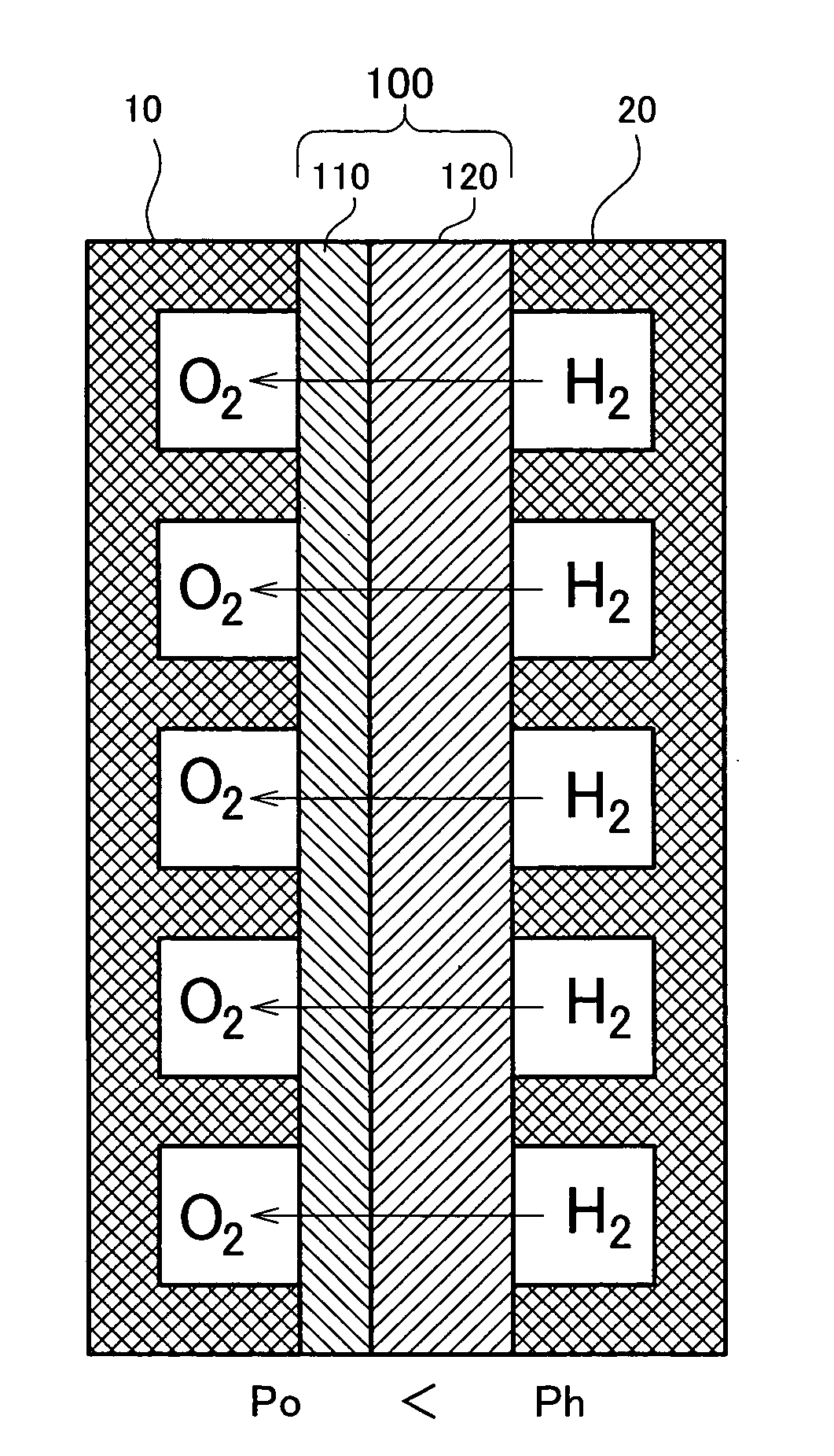
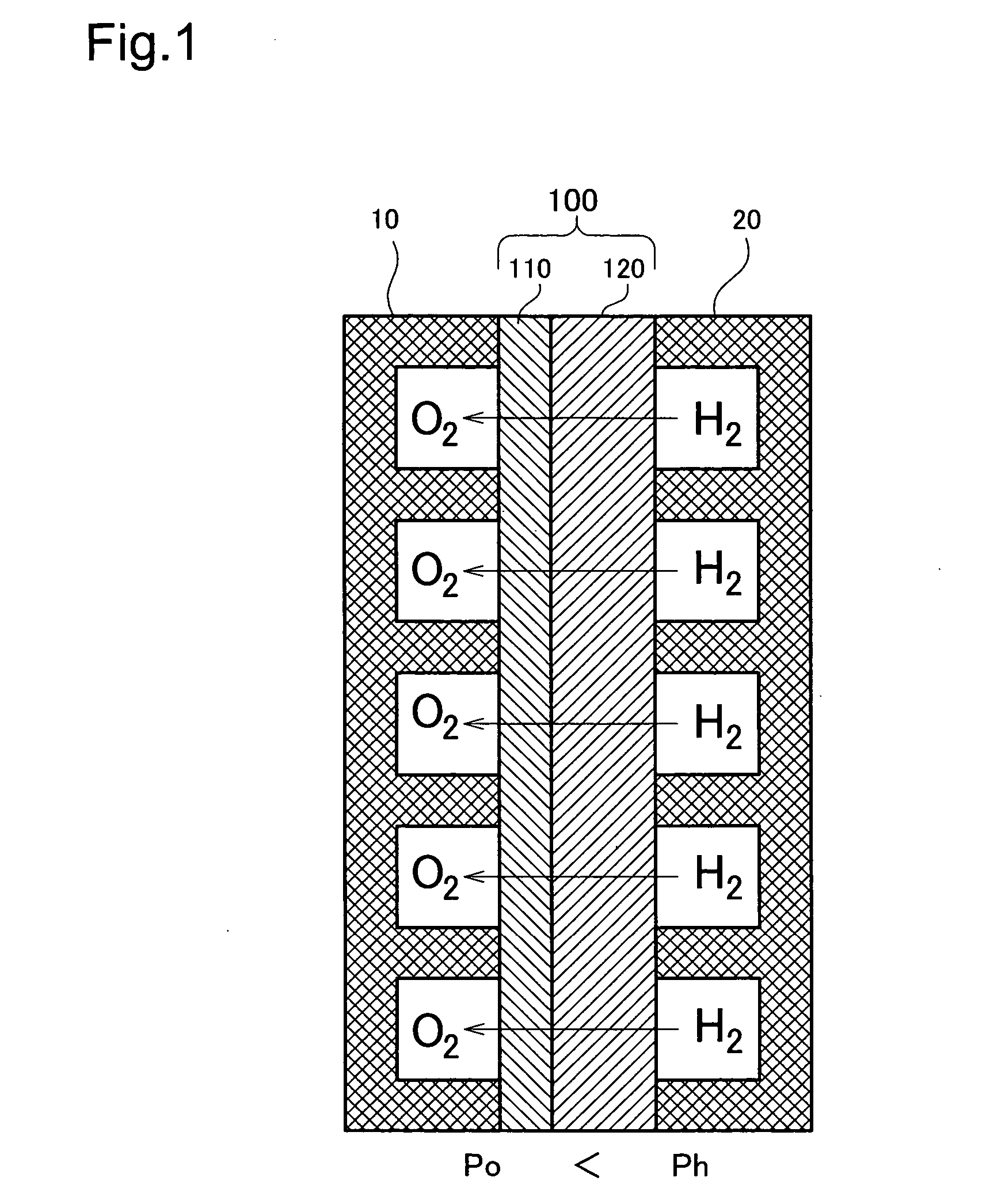
[0078]FIG. 1 is a model diagram depicting the overall arrangement of the fuel cell of A cell making up the fuel cell is shown in cross section. This cell has a structure wherein an electrolyte membrane 100 is sandwiched between an oxygen electrode 10 (hereinafter sometimes designated as the cathode) and a hydrogen electrode 20 (hereinafter sometimes designated as the anode). The structure and material of the oxygen electrode 10 and the hydrogen electrode 20 can be formed of various materials such as carbon.

[0079] The electrolyte membrane 100 has a thin electrolyte layer 110 of a solid oxide formed on the surface of a fine hydrogen-permeable metal layer 120 of vanadium (V). The electrolyte layer 110 may consist of a BaCeO3 or SrCeO3 based ceramic proton conductor. A coating of palladium (Pd) may be formed on the outside of the electrolyte layer 110. In this embodiment, the electrolyte layer 110 thickness is 1 μm, and the hydrogen-permeable metal layer 120 thickness is 40 μm. The thi...

case a1

[0091] Case A1 is an example in which the contact interface is partial, and the anode is arranged to the outside. As with the Embodiment, a skeletal frame member 126A is disposed around hydrogen-permeable metal 121A. However, on the anode contact face (upper face in the drawing), the skeletal frame member 126A is not exposed. Accordingly, the hydrogen-permeable metal 121A can contact the anode over its entire face, so that migration of hydrogen proceeds smoothly, and thus membrane resistance can be reduced.

[0092] Case B1 is an example in which the contact interface is partial, and the anode is arranged to the inside. As with Embodiment 1, hydrogen-permeable metal 121B is disposed within recesses in a skeletal frame member 126B. The anode 20B is arranged on the upper face of the hydrogen-permeable metal 121B. With this construction, by making the hydrogen-permeable metal 121B thin, the rate of hydrogen permeation and be improved, and thus membrane resistance can be reduced.

[0093] Ca...


PUM


Abstract

The present invention has as an object to produce a thinner electrolyte layer in a solid oxide type fuel cell. In a solid oxide type fuel cell, a solid oxide electrolyte layer 110 is grown on the surface of a hydrogen-permeable metal layer 120. A structure is provided for preventing interlayer separation of the hydrogen-permeable metal layer 120 and the electrolyte layer 110 due to expansion of the hydrogen-permeable metal layer 120 during permeation of hydrogen. As the separation preventing mechanism, there can be employed a structure that prevents expansion of the hydrogen-permeable metal layer 120, or a structure wherein the electrolyte layer is divided to ameliorate stress during expansion. By so doing, the electrolyte layer can be thinned sufficiently.

Description

TECHNICAL FIELD [0001] The present invention relates to a fuel cell employing an electrolyte membrane that comprises a hydrogen-permeable metal layer. BACKGROUND ART [0002] In recent years, fuel cells that generate electricity through an electrochemical reaction of hydrogen and air have attracted notice as an energy source. Types of fuel cells currently available that use solid electrolyte membranes include high temperature type fuel cells of solid oxide type and the like. [0003] Fuel cells of solid oxide type typically employ a thin membrane of zirconia or other inorganic substance as the electrolyte membrane sandwiched between the electrodes. The membrane resistance of such electrolyte membranes tends to increase at lower temperatures, and thus in order to keep membrane resistance within a practicable range, operation at relatively high temperature is necessary. [0004] In fuel cells of solid oxide type, while it is possible to reduce the membrane resistance by reducing the thickne...

Claims


Application Information

Patent Timeline
IPC IPC(8): H01M8/02H01M8/10B05D5/12H01M4/86H01M4/94H01M8/06H01M8/12
CPCH01M4/8642H01M4/8657H01M4/94H01M8/0297H01M8/0687H01M8/1004H01M8/1006H01M8/1016H01M8/122Y02E60/521Y02E60/525Y02E60/50Y02P70/50H01M8/241
Inventor SATO, HIROMICHIOGINO, SHIGERUIGUCHI, SATOSHIIIJIMA, MASAHIKOITO, NAOKIAOYAMA, SATOSHIENO, HIROTAKA
Owner TOYOTA JIDOSHA KK
Why Eureka
Try Eureka