
Analyte test sensor and method of manufacturing the same

a technology of analyte test and sensor, which is applied in the field of electrochemical test sensors, can solve the problems of piercing of the skin of the patient, inaccurate glucose level readings calculated therefrom, and variances of different batches of test strips, etc., and achieves the effect of convenient use and low manufacturing cos

Inactive Publication Date: 2006-07-06
ABBOTT DIABETES CARE INC
View PDF13 Cites 212 Cited by
  • Summary
  • Abstract
  • Description
  • Claims
  • Application Information

AI Technical Summary

Benefits of technology

[0024] It is still another object of the present invention to provide a test sensor of the type described above which has a limited number of parts, which is inexpensive to manufacture and which is easy to use.

Problems solved by technology

Typically, the movement of the lancet from its retracted position to its extended position is effected with such force that contact of the moving lancet tip with the skin of a patient results in the piercing of the skin of the patient.
Due to inevitable inconsistencies in manufacturing, variances often arise between different batches of test strips (e.g., the size of the working and reference electrodes, the amount of enzyme deposited on the working electrode, etc.).
As can be appreciated, any alteration of the value of the measured working current can render the glucose level reading calculated therefrom potentially inaccurate, which is highly undesirable.
First, the use of an independent calibration strip requires a patient to perform the time-consuming and complicated task of digitally calibrating a blood glucose meter prior to performing an assay using a test strip from its associated batch.
Second, the use of an independent calibration strip in conjunction with a batch of test strips significantly increases the overall manufacturing costs for said batch, this increase in manufacturing costs being a direct consequence of the costly memory requirement for the calibration strip.
One drawback associated with the aforementioned test strip is the limited number of calibration codes that it can accommodate.
However, it has been found that manufacturing tolerances often require a relatively large number of different calibration codes (e.g., often as many as 50 calibration codes are required).
Consequently, the limited number of calibration codes afforded by such a test strip has been found to be inadequate.

Method used


Image

  • Analyte test sensor and method of manufacturing the same
  • Analyte test sensor and method of manufacturing the same
  • Analyte test sensor and method of manufacturing the same

Examples


first embodiment

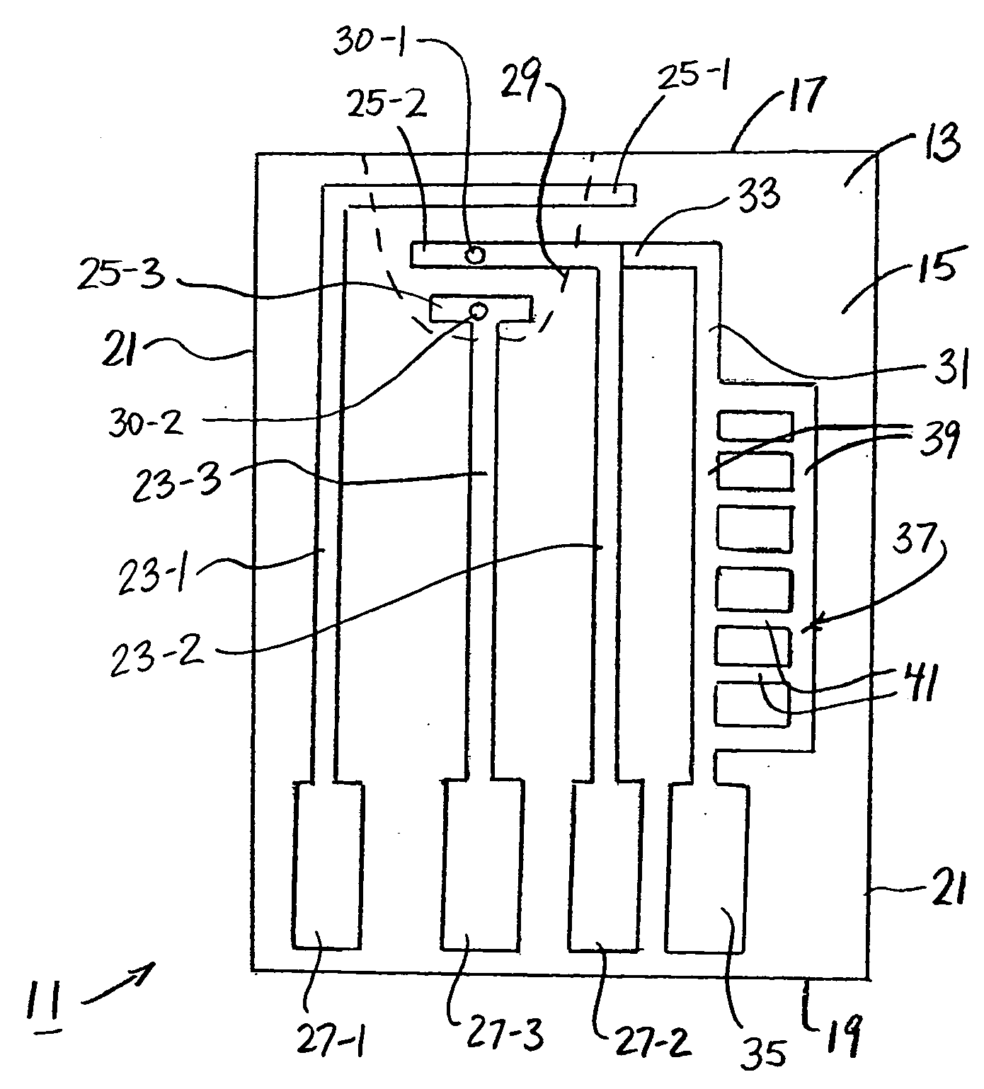
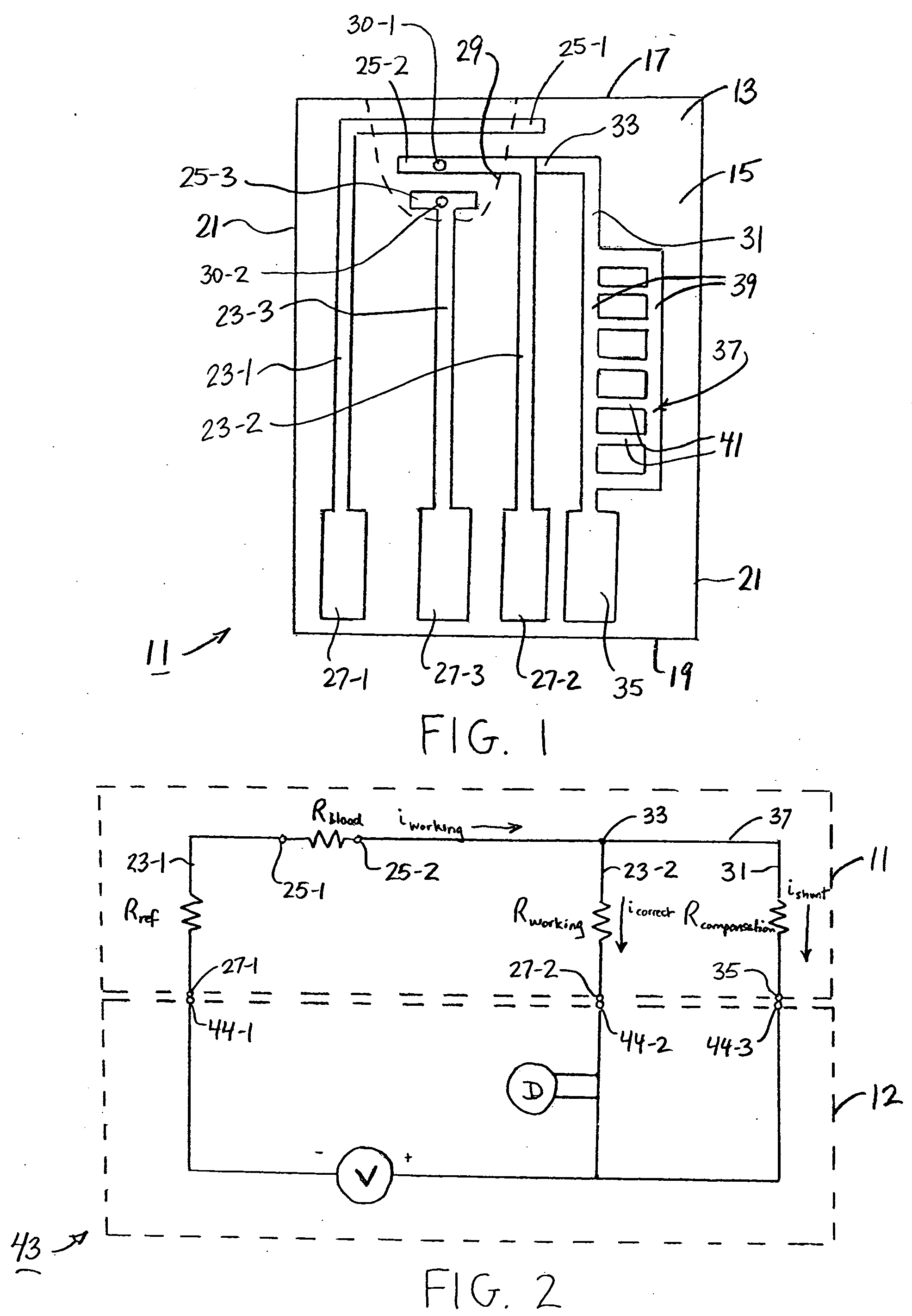
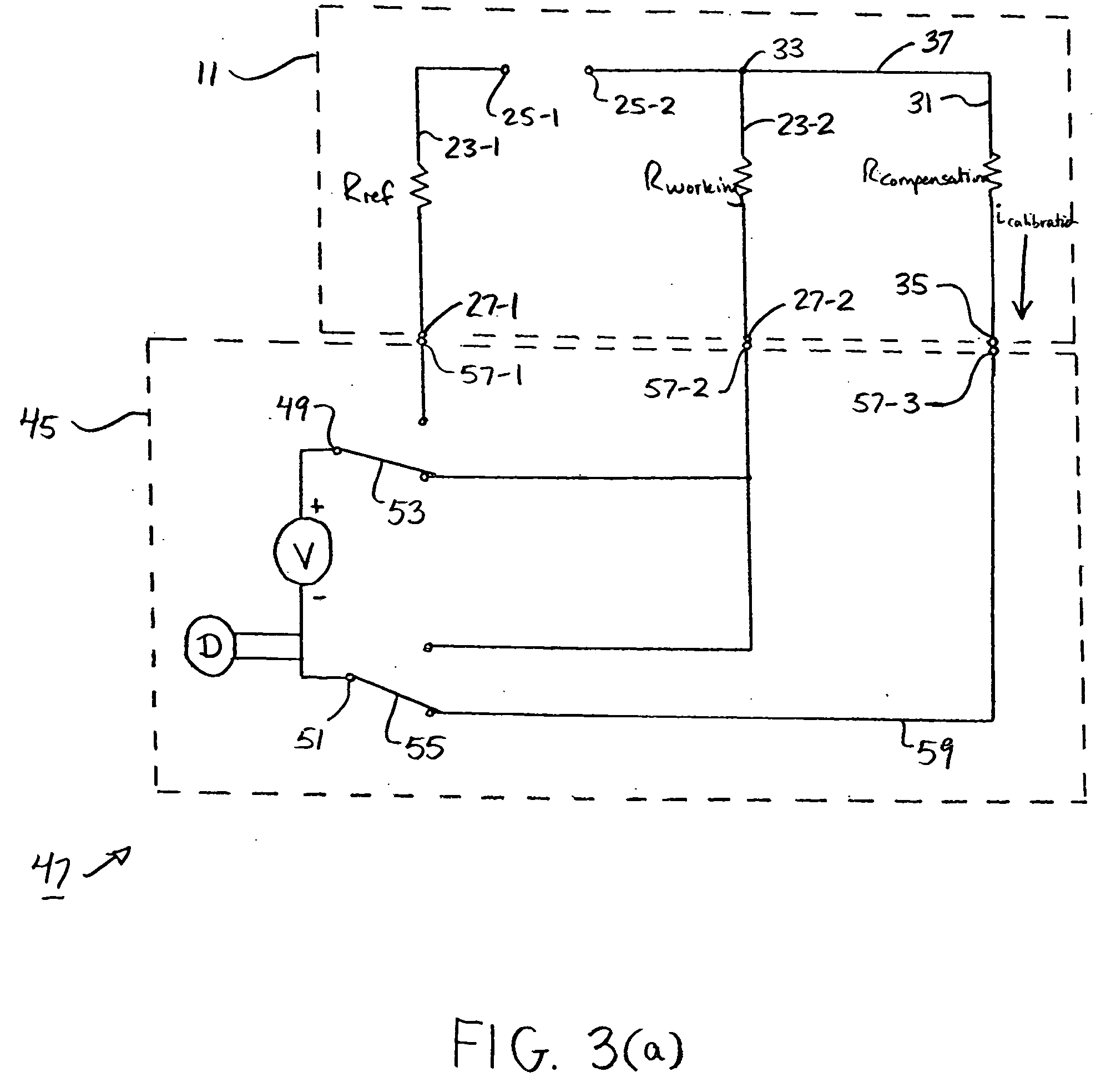
[0034] Referring now to the drawings, there is shown in FIGS. 1 and 2 an electrochemical test sensor that is constructed according to the teachings of the present invention, the electrochemical test sensor being identified generally by reference numeral 11. In use, test sensor 11 can be used, in conjunction with a compatible analyte test meter 12, to calculate the concentration of a particular analyte in a test sample. Furthermore, as a principal feature of the present invention, test sensor 11 is provided with means for correcting test result inaccuracies which are the result of common variances in manufacturing, as will be described further below.

[0035] As seen most clearly in FIG. 1, test sensor 11 (also referred to herein as test strip 11) includes a unitary, non-conductive substrate 13 which is preferably constructed of plastic using conventional molding techniques. Substrate 13 is preferably formed into a rectangular strip which includes a substantially flat top surface 15, a ...

second embodiment

[0077] It is to be understood that the particular construction of test strip 11 could be modified without departing from the spirit of the present invention. For example, referring now to FIG. 4, there is shown a test strip constructed according to the teachings of the present invention, the test strip being identified by reference numeral 111. As will be described further below, test strip 111 is similar to test strip 11 in that test strip 111 includes on-board means for performing digital calibration.

[0078] Test strip 111 is identical in construction to test strip 11 in all respects with one notable exception. Specifically, test strip 111 includes a compensation electrode 131 of a slightly different design than compensation electrode 31 in test strip 11.

[0079] Compensation electrode 131 is similar in construction to compensation electrode 31 in that compensation electrode 131 includes a first end 133, a second end 135 and a resistive ladder 137 formed thereinto along a portion of...


PUM

PropertyMeasurementUnit
Concentrationaaaaaaaaaa
Electrical resistanceaaaaaaaaaa
Currentaaaaaaaaaa

Abstract

An analyte test sensor for use in measuring the concentration of a particular analyte in a test sample includes a non-conductive substrate, a reference electrode deposited on the substrate, a working electrode deposited on the substrate and a compensation electrode deposited on the substrate. The compensation electrode is provided with a resistive ladder and is designed to correct for test result inaccuracies which are the result of variances in the manufacturing of the test sensor. Specifically, in one embodiment, the compensation electrode corrects for test result inaccuracies in an analog manner by shunting a portion of the working current away from working electrode. In another embodiment, the compensation electrode corrects for test result inaccuracies in a digital manner by providing a calibration code which is proportional its resistance value. A batch of analyte test sensors are preferably manufactured in the following manner. An initial batch of the test sensors is constructed. Then, a limited sampling of the sensors is tested for accuracy using a control sample. Based on the test results, the resistance value of the compensation electrode for each remaining sensor in the batch is adjusted accordingly.

Description

BACKGROUND OF THE INVENTION [0001] The present invention relates generally to test sensors and more particularly to electrochemical test sensors. [0002] There are many medical conditions which require frequent measurement of the concentration of a particular analyte in the blood of a patient. For example, diabetes is a disease which typically requires a patient to routinely measure the concentration of glucose in his / her blood. Based upon the results of each blood glucose measurement, the patient may then require a particular drug treatment (e.g., an injection of insulin) in order to regulate that the blood glucose level of the patient remains within a specified range. Exceeding the upper limit of said range (hyperglycemia) or dropping beneath the lower limit of said range (hypoglycemia) should be avoided with as much diligence as possible to prevent the patient from experiencing serious medical complications which include, inter alia, retinopathy, nephropathy, and neuropathy. [0003...

Claims


Application Information

Patent Timeline
IPC IPC(8): G01N33/487A61B5/05
CPCG01N27/4175G01N31/00C12Q1/001G01N27/04G01N27/3274C12Q1/006G01N27/4163G01N33/48771
Inventor GHESQUIERE, ALEXANDER G.TONKS, SIMON
Owner ABBOTT DIABETES CARE INC
Learn More