Propellant tank baffle system

a technology of pressure tank and baffle, which is applied in the field of gas pressurization systems, can solve the problems of high pressure pressure vessel weight too heavy if made from metal, the effect of reducing the mass of gas, reducing mixing, and reducing the circulation of pressure gas

Inactive Publication Date: 2006-07-06
BUEHLER DAVID BENJAMIN
View PDF20 Cites 32 Cited by
  • Summary
  • Abstract
  • Description
  • Claims
  • Application Information

AI Technical Summary

Benefits of technology

[0017] The pressurant gas is delivered hot, to reduce the mass of gas required to fill the volume of the pressure vessel at the target pressure. The diffuser deflects the flow of the pressurant gas as it enters the pressure vessel, reducing mixing of the entering gas with cooler gas inside the vessel, and preventing the stream of entering gas from blowing directly on the cold propellant. The baffle further reduces circulation of the pressurant gas, and reduces the sloshing of propellant, thus reducing both contact between the propellant and gas, and sloshing-induced circulation of gas.
[0018] The pressurant gas heater has a controller which controls the temperature the pressurization gas it heated to before it is introduced into the pressure vessel propellant tank. The controller initially causes cooler gas to be introduced into the tank, and then gradually raises the temperature over the duration of the engine burn on the rocket stage. This minimizes the thermal shock on the walls of the pressure vessel. The thrust that the stage is under due to the rocket engine firing helps keep the gas in stratified layers, so a given point of the pressure vessel wall experiences a gradual increase in local gas temperature.
[0019] The pressure vessel is constructed with baffles assembled with feet springs locked. The composite pressure vessel wall is wound around the assembled baffle system. After the mandrel is removed, adhesive is injected under the feet, and the fixed feet and spring feet are afixed to the pressure vessel. This allows the metal baffles to expand and contract without loading the pressure vessel structure.

Problems solved by technology

A problem with using hot gas is that the propellant can cool the gas.
This is particularly true in the case of cryogenic propellant, and in cases where the propellant sloshes within the tank, the cooling may occur in an unpredictable manner.
Pressure fed vehicles offer a possible route to low cost, but the problem is that high pressure pressure vessels are too heavy if made from metal.
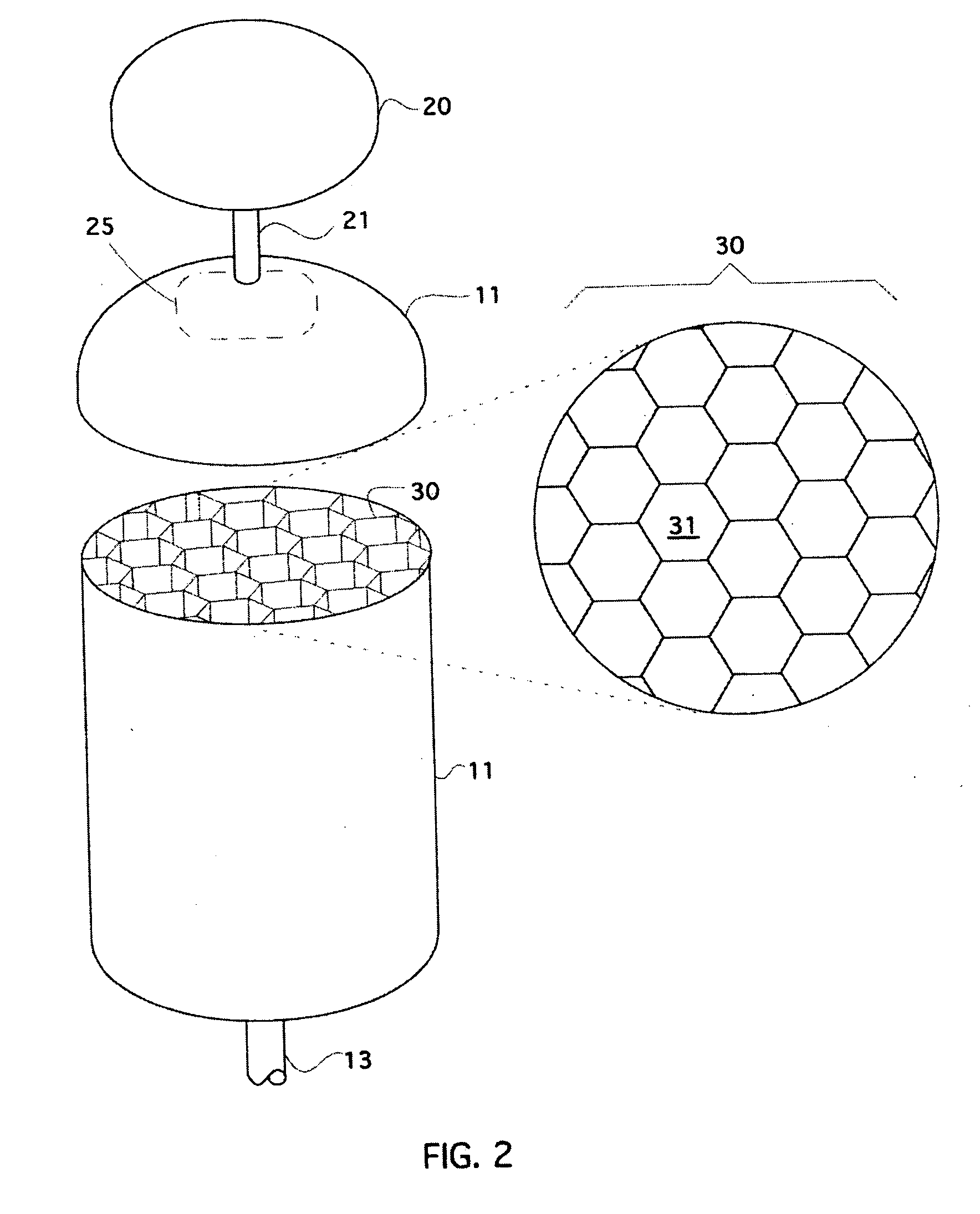
Pressure vessels need baffles for slosh control and to prevent gas mixing, but composite baffles for LOX would be a hazard, and metal baffles put differential thermal expansion induced loads on the composite pressure vessel.

Method used


Image

  • Propellant tank baffle system
  • Propellant tank baffle system
  • Propellant tank baffle system

Examples


Embodiment Construction

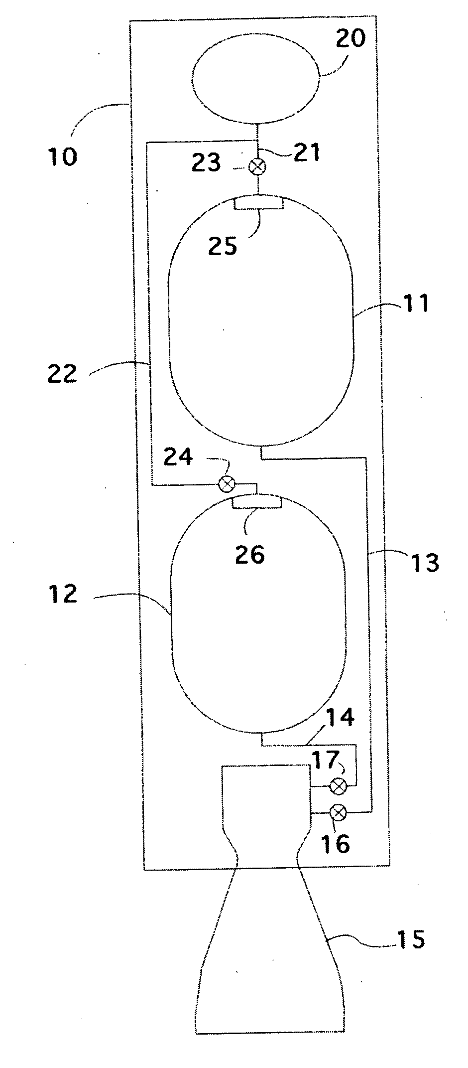
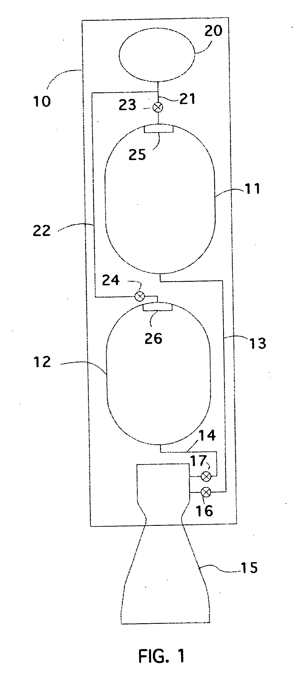
[0033] Referring to FIG. 1, the invention is installed on a rocket stage 10, to provide pressure to force propellant from propellant tanks 11 and 12 through propellant conduits 13 and 14 and into the combustion chamber of the engine 15. Flow of propellant into the engine 15 is regulated by propellant regulators 16 and 17. Hot pressurant gas is provided by the pressurant gas source 20. Pressurant gas is delivered to propellant tanks 11 and 12 via pressurant gas conduits 21 and 22. Flow of pressurant gas into propellant tanks 11 and 12 is regulated by pressurant regulators 23 and 24. Diffusers 25 and 26 diffuse the pressurant gas as it enters the propellant tanks. The invention could be used on both the fuel and oxidizer tank, or just the fuel tank, or just the oxidizer tank.

[0034] The pressurant gas source 20 includes a gas stored at high pressure, or a gas generator. In the case of the gas stored at high pressure, preferably the gas source 20 would also include a heater, to heat th...


PUM


Abstract

The invention disclosed here is a pressurization system for pressure-fed launch vehicles. The system employs a hot pressurant gas to minimize the mass of pressurant gas required. It also employs a set of baffles within the propellant tank to reduce heat transfer between the propellant and the hot pressurant gas. The baffles keep the pressurant gas flowing uniformly in one direction as the propellant is expelled, and inhibit mixing of the cold gas near the propellant with the hot gas being blown into the tank. The baffles also prevent large-scale sloshing of the propellant. The metal baffles are rigidly attached to one end of the tank and attached with a mount which allows travel in the longitudinal direction but not in the two lateral directions which minimizes stess on the pressure vessel from differences in thermal expansion.

Description

[0001] This application claims the benefit of provisional applications No. 60 / 634,863 filed Dec. 10, 2004 entitled “Composite propellant tank with a system of metal baffles”, and provisional applications No. 60 / 634,864 filed Dec. 10, 2004 entitled “Hot gas pressurization system utilizing baffles”. [0002] It also references USPTO disclosure document number 549182 filed Mar. 15, 2004, entitled “Composite Propellant Tank With A System of Metal Baffles”.BACKGROUND OF THE INVENTION [0003] 1. Field of the Invention [0004] This invention relates to gas pressurization systems. Gas pressurization systems are used to maintain pressure within a pressure vessel filled with fluid while the fluid is being expelled. More specifically, it relates to gas pressurization systems employed on rocket stages. [0005] 2. Description of Related Art [0006] This invention in its main embodiment is intended for use in a rocket vehicle. Rocket vehicles can be either pump-fed or pressure-fed. In a pump-fed vehicl...

Claims


Application Information

Patent Timeline
Patent Type & Authority Applications(United States)
IPC IPC(8): B64G1/00
CPCB64G1/402F02K9/50
Inventor BUEHLER, DAVID BENJAMIN
Owner BUEHLER DAVID BENJAMIN
Why Eureka
Try Eureka