Perpendicular magnetic recording medium

Inactive Publication Date: 2006-07-06
FUJI ELECTRIC DEVICE TECH CO
View PDF7 Cites 11 Cited by
  • Summary
  • Abstract
  • Description
  • Claims
  • Application Information

AI Technical Summary

Benefits of technology

[0017] In view of the above problems, an object of the present invention is to provide a perpendicular magnetic recording medium exhibiting excellent magnetic recording performance by

Problems solved by technology

One of the problems in a perpendicular magnetic recording medium having such a structure is that spike noise, a type of noise generated from a medium, is known to be caused by magnetic domain walls formed in the soft magnetic backing layer.
To ensure proper magnitude of the exchange coupling and suppress the formation of the magnetic domain wall, simple lamination of an antiferromagnetic layer and a soft magnetic backing layer is not effective.
Thus, an excessively thick nonmagnetic underlayer is unfavorable.
However, study by the present inventors has revealed that a nonm

Method used


Image

  • Perpendicular magnetic recording medium
  • Perpendicular magnetic recording medium
  • Perpendicular magnetic recording medium

Examples


example 1

[0050] The nonmagnetic substrate used was a strengthened glass substrate with a disk shape having a nominal diameter of 2.5 inches (N-5 manufactured by HOYA Corporation). After cleaning, the substrate was introduced into a sputtering apparatus. Soft magnetic backing layer 2 having a thickness of 150 nm was formed of a NiFe alloy having an fcc structure under an argon gas pressure of 5 mTorr using a target of a Ni22Fe alloy. (The numeral represents atomic percent of the following element, namely, 22 at % of Fe and the remainder of Ni. The same notation applies in the following descriptions.) Subsequently, antiferromagnetic layer 3 was formed of an IrMn alloy having an fcc structure under an argon gas pressure of 20 mTorr using a target of Ir80Mn alloy. The thicknesses of the antiferromagnetic layers were varied in the range of zero to 10 nm. Subsequently, nonmagnetic underlayer 4 having a thickness of 10 nm was formed of ruthenium having an hcp structure under an argon gas pressure o...
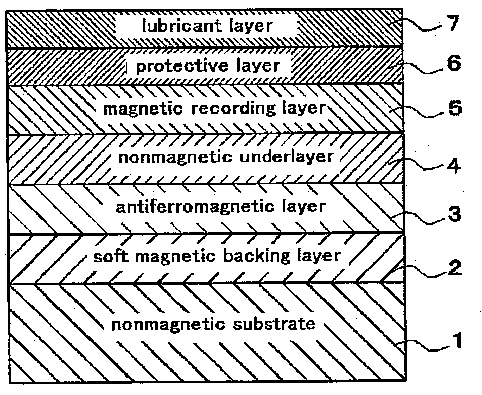
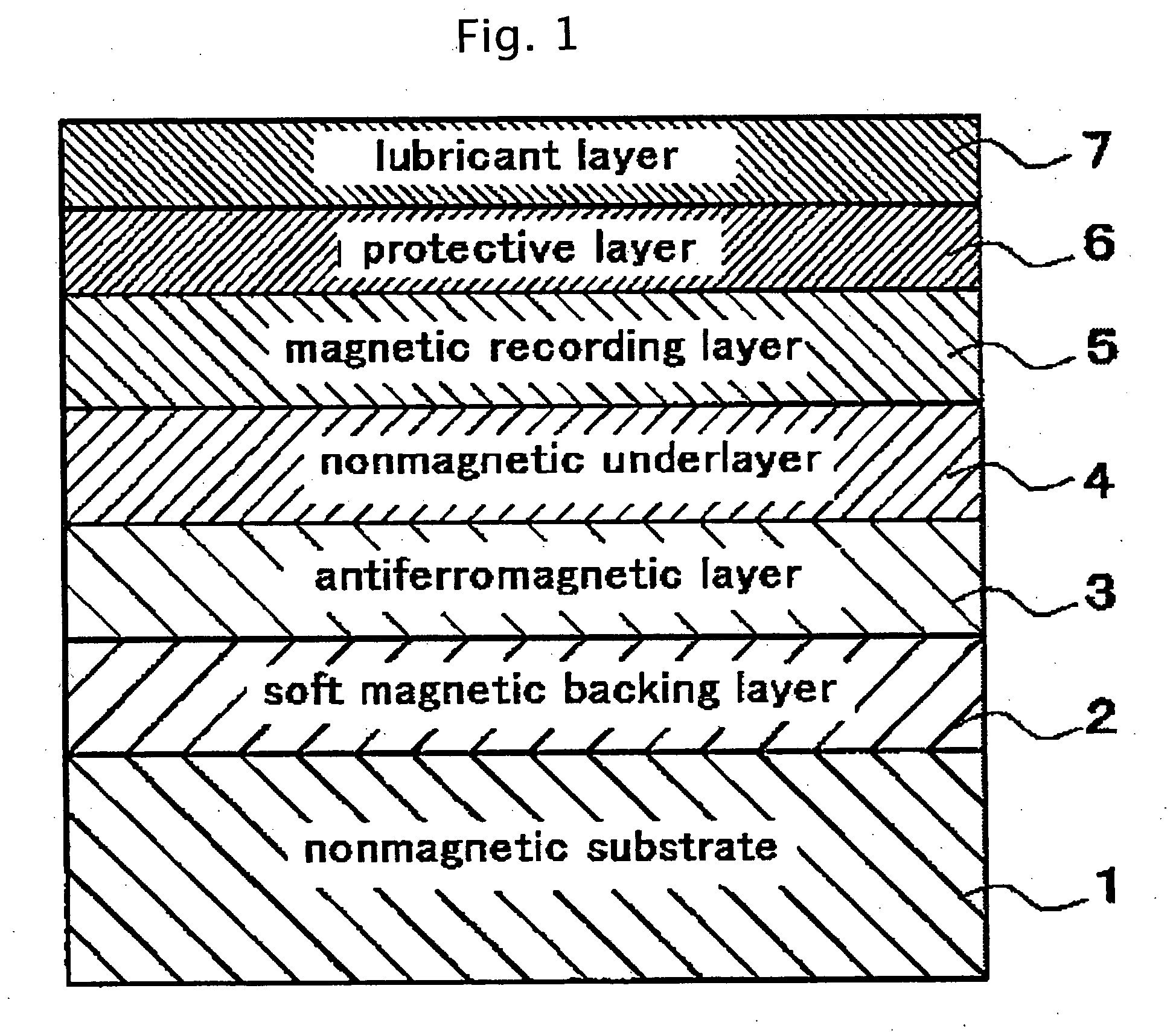
example 2

[0054] Perpendicular magnetic recording media having a structure of FIG. 1 were manufactured in the same manner as in Example 1 except that the thickness of the antiferromagnetic layer was fixed to 5 nm and the thickness of the nonmagnetic underlayer was varied in the range of zero to 25 nm.
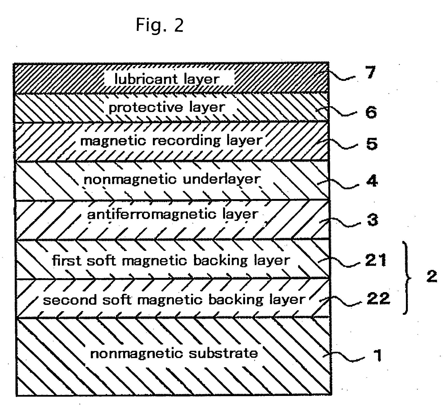
example 3

[0055] Perpendicular magnetic recording media having a structure of FIG. 2 were manufactured in the same manner as in Example 2 except that after cleaned nonmagnetic substrate was introduced into a sputtering apparatus, second soft magnetic backing layer 22 having a thickness of 120 nm was formed of a CoZrNb alloy having an amorphous structure under an argon gas pressure of 5 mTorr using a target of Co5Zr5Nb and subsequently first soft magnetic backing layer 21 having a thickness of 30 nm was formed of a NiFe alloy.


PUM


Abstract

A perpendicular magnetic recording medium is provided that achieves excellent magnetic performance by suppressing spike noises due to a soft magnetic backing layer, as well as good productivity. The perpendicular magnetic recording medium comprises at least a soft magnetic backing layer, an antiferromagnetic layer, an nonmagnetic underlayer, and a magnetic recording layer sequentially laminated on a nonmagnetic substrate, wherein the magnetic recording layer has a granular structure, the nonmagnetic underlayer is composed of ruthenium or a ruthenium alloy having an hcp structure having a thickness of at least 5 nm, the antiferromagnetic layer is composed of an alloy having an fcc structure and containing at least manganese, and the antiferromagnetic layer is laminated directly on the soft magnetic backing layer. Preferably, the antiferromagnetic layer is composed of an IrMn alloy, and the soft magnetic backing layer has an fcc structure and contains at least nickel and iron. Advantageously, the soft magnetic backing layer consists of two or more directly laminated soft magnetic layers, and a distance between a top surface of the soft magnetic backing layer and a bottom surface of the magnetic recording layer is at most 25 nm.

Description

CROSS REFERENCE TO RELATED APPLICATIONS [0001] This application is based on, and claims priority to, Japanese Application No. 2004-349550, filed on Dec. 2, 2004, the contents of which are incorporated herein by reference. BACKGROUND OF THE INVENTION [0002] A. Field of the Invention [0003] The present invention relates to a perpendicular magnetic recording medium installed in a magnetic recording apparatus, including an external storage device of a computer. [0004] B. Description of the Related Art [0005] In place of conventional longitudinal magnetic recording systems, a perpendicular magnetic recording system is drawing attention as a technology to achieving high density magnetic recording. A double layer perpendicular magnetic recording medium, in particular, is known as a favorable perpendicular magnetic recording medium to achieve high recording density. A double layer perpendicular magnetic recording medium is provided with a soft magnetic film, called a soft magnetic backing l...

Claims


Application Information

Patent Timeline
IPC IPC(8): G11B5/66
CPCG11B5/667G11B5/7325G11B5/737
Inventor UWAZUMI, HIROYUKISAKAI, YASUSHITAKENOIRI, SHUNJIWATANABE, SADAYUKI
Owner FUJI ELECTRIC DEVICE TECH CO
Why Eureka
Try Eureka