Humidifier for fuel cell system

Inactive Publication Date: 2006-07-06
HONDA MOTOR CO LTD
View PDF1 Cites 34 Cited by
  • Summary
  • Abstract
  • Description
  • Claims
  • Application Information

AI Technical Summary

Benefits of technology

[0015] In addition, an inside face of the head portion and at least one surface of the flow passage control member may be dispensed with a water repellent treatment. In a case of the water repellent treatment not being dispensed, produced water adheres to the inside face of the head portion and the surface of the flow passage control member, the water is apt to remain on a wall face, and there is a possibility that the water adhered to the inside face of the head portion and the surface of the flow passage control member flows at a breath toward the fuel cell at start of the fuel cell system; whereas in a case of the water repellent treatment being dispensed, it does not occur that the produce

Problems solved by technology

An ion exchange membrane such as a fluorocarbon resin group cited as one of solid polymers functions as a proton conductive electrolyte membrane in a water containing state; however, in a dry state its proton conductivity lowers and it causes a lowering of a power output.
Therefore, if the fuel cell system is started in this state, the condensation water accumulated in the vicinity of t

Method used


Image

  • Humidifier for fuel cell system
  • Humidifier for fuel cell system
  • Humidifier for fuel cell system

Examples


first embodiment

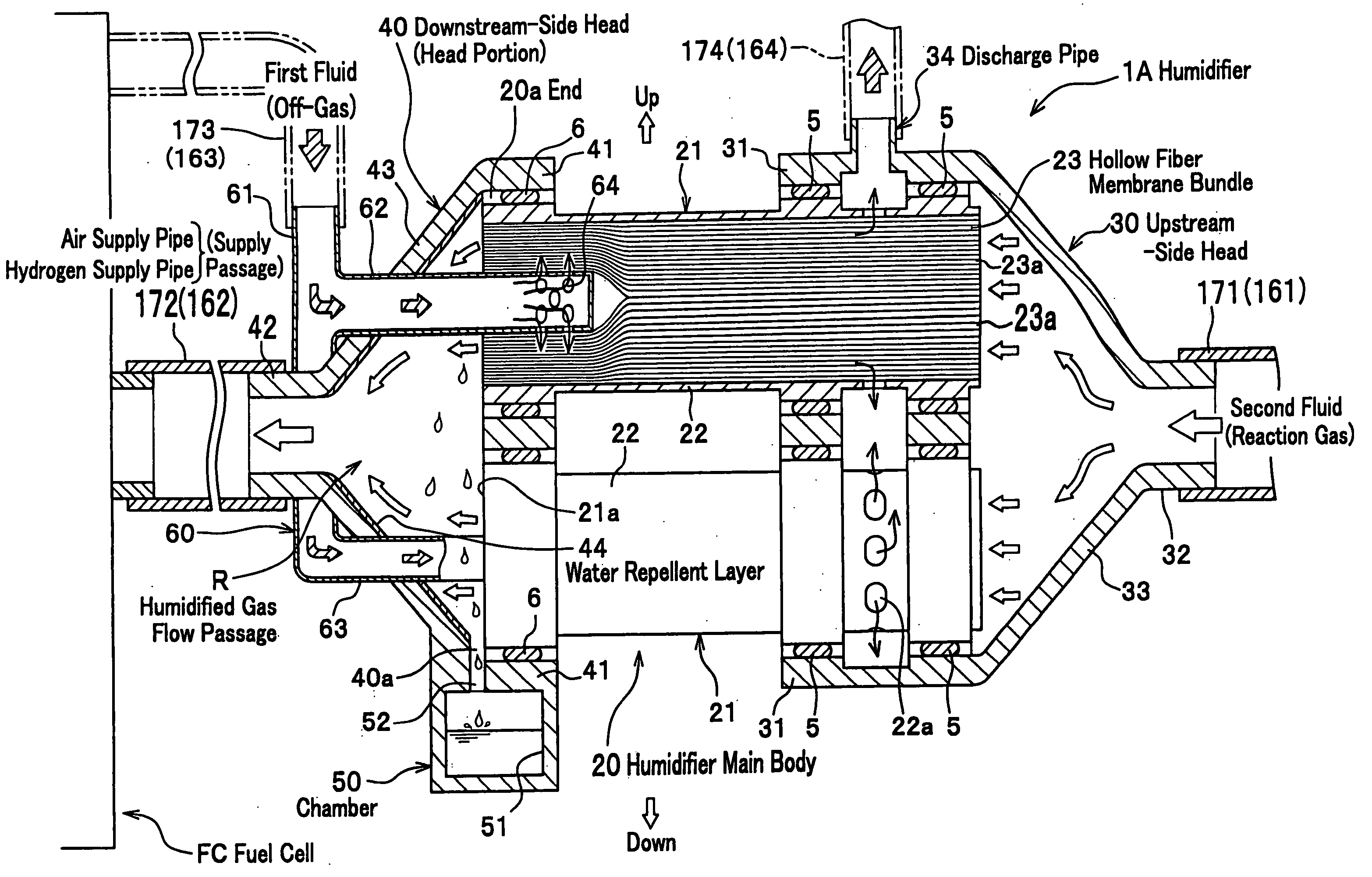
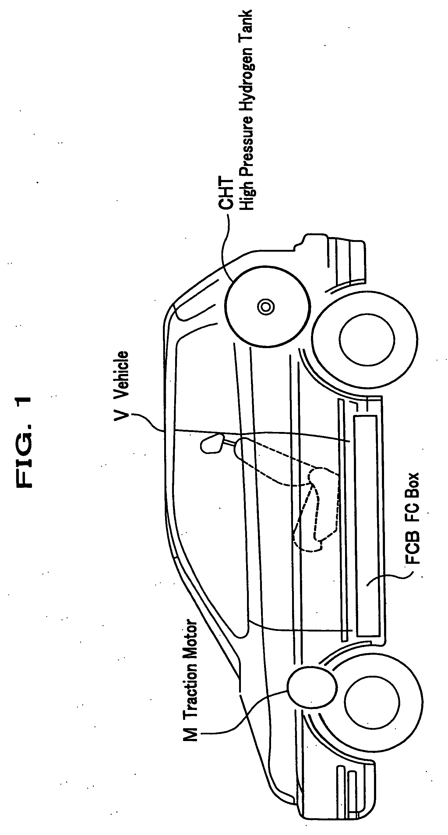
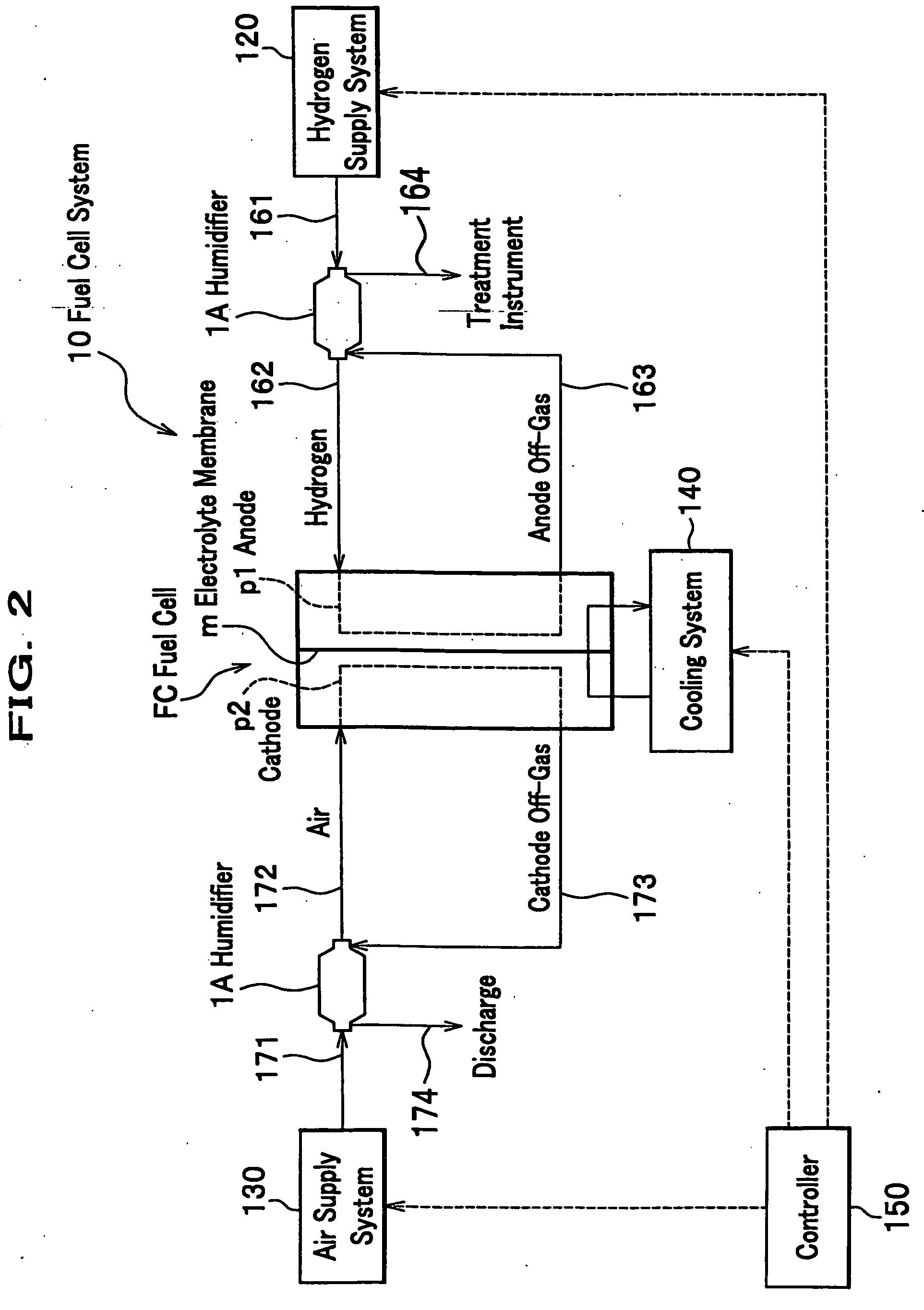
[0024]FIG. 1 is a partial perspective side view of a vehicle where a fuel cell system related to the present invention is mounted. FIG. 2 is a block diagram showing a humidifier related to the present invention. FIG. 3 is a vertical section view of a humidifier of a first embodiment. Meanwhile, here will be described a case of the fuel cell system and the humidifier being mounted on a vehicle, the present invention is not limited thereto and is applicable to an airplane and a ship.

[0025] As shown in FIG. 1, in a vehicle V of the present invention a FC (fuel cell) box FCB is mounted below a floor of a passenger seat, and a fuel cell FC (see FIG. 2) is housed in the FC box FCB. In addition, in the vehicle V is mounted a traction motor M at a front portion of a vehicle body, and a high pressure hydrogen tank CHT is horizontally mounted above a rear wheel.

[0026] As shown in FIG. 2, a fuel cell system 10 mounted on the vehicle V comprises the fuel cell Fe, a hydrogen supply system 120,...

second embodiment

[0049]FIG. 5 is a vertical section view of a humidifier of a second embodiment. FIG. 6 is a section view of a VI-VI line in FIG. 5. A difference between the humidifier 1A and a humidifier 1B of the second embodiment exists in a point that a flow passage control member 70 of a labyrinth structure is provided within the downstream-side head 40 instead of the chamber 50. With respect to other configurations, appending same symbols as in the first embodiment, descriptions thereof will be omitted.

[0050] As shown in FIGS. 5 and 6, the flow passage control member 70 comprises partition plates 71a, 71b, 71c, 71d, and 71e (see FIG. 6). Each of the partition plates 71a to 71e is integrally provided with the downstream-side head 40 by a metal material at a position opposing the outlet portion 21a of one (lower) hollow fiber module 21 of the humidifier main body 20. The partition plate 71a extends in a horizontal direction (direction of the outlet portion 21a of the hollow fiber module 21, and...

third embodiment

[0055]FIG. 8 is a vertical section view of a humidifier of a third embodiment. A humidifier 1C of the third embodiment is a configuration where a water drain pipe (water drain passage) 80 comprises an orifice 81 functioning as a flow rate adjustment mechanism, and is added to the humidifier 1A of the first embodiment. In addition, in the third embodiment a configuration of a downstream-side head 40A is different from those of the first and second embodiments.

[0056] Whole of the downstream-side head (head portion) 40A is formed of a synthetic resin material, and comprises a pair of larger diameter hold portions 45, 45; a tube joint portion 46 smaller than the hold portions 45, 45 in diameter extending till a connection portion 90 provided at the fuel cell FC; and a narrow down portion 47 for connecting the hold portions 45, 45 to the joint portion 46. In other words, the downstream-side head 40A of the head portion is formed, integrally extending from an end of the humidifier main b...


PUM


Abstract

A humidifier of the present invention includes a humidifier main body for humidifying a second fluid, using a humidified first fluid discharged from a fuel cell; a head portion of which one end is connected to an end of the humidifier main body and the other end is connected to the fuel cell or a supply passage extending from the fuel cell, and which supplies the second fluid after humidification to the fuel cell; and a chamber for communicating a bottom portion of a humidified gas flow passage formed within the head portion.

Description

BACKGROUND OF THE INVENTION [0001] 1. Field of the Invention [0002] The present invention relates to a humidifier for humidifying a dry fluid, using moisture in a humidified fluid. [0003] 2. Description of the Related Art [0004] As a fuel cell for a fuel cell electric vehicle (FCEV) is generally adopted, for example, a PEM (Proton Exchange Membrane) type using a solid polymer as an electrolyte membrane because of a small size and light weight, high efficiency, and high power output thereof. An ion exchange membrane such as a fluorocarbon resin group cited as one of solid polymers functions as a proton conductive electrolyte membrane in a water containing state; however, in a dry state its proton conductivity lowers and it causes a lowering of a power output. Therefore, a fuel cell system equipped with this kind of a fuel cell is designed to humidify reaction gases (anode gas and cathode gas) supplied to an anode and cathode of the fuel cell by a humidifier so that an electrolyte mem...

Claims


Application Information

Patent Timeline
IPC IPC(8): H01M8/04B01D53/22
CPCB01D53/265B01D53/268H01M8/04149H01M8/04164H01M2008/1095H01M2250/20Y02E60/50Y02T90/32Y02T90/40
Inventor SUZUKI, MOTOHIROKATAGIRI, TOSHIKATSUKUSANO, YOSHIONAGUMO, KENJI
Owner HONDA MOTOR CO LTD
Why Eureka
Try Eureka