Magnetoresistance effect elements, magnetic heads and magnetic storage apparatus

a technology of magnetic effect and magnetic recording medium, which is applied in special recording techniques, magnetic bodies, instruments, etc., can solve the problems of insufficient ferromagnetic ni layer and co layer intersection to precisely detect the magnetic field in a narrow region, and the magnetic flux change associated with the signal recorded in a narrow track cannot be detected with a high sensitivity, so as to achieve high sensitivity and high resolution

Inactive Publication Date: 2006-07-13
HITACHI GLOBAL STORAGE TECH NETHERLANDS BV
View PDF32 Cites 7 Cited by
  • Summary
  • Abstract
  • Description
  • Claims
  • Application Information

AI Technical Summary

Benefits of technology

[0011] Accordingly, it is an object of the invention to provide a magnetoresistance effect element capable of sensing a very small change of magnetic flux from a narrow region of a magnetic recording medium with high sensitivity and with high resolution.
[0037] As described above, in the element having the Fe / Cr multilayered films and the element having the magnetoresistance effect due to the multilayered structure such as the ferromagnetic tunneling element, the electrical resistance of the whole element can be increased and a large amount of resistance change can be obtained by series connection of a plurality of magnetoresistance effect elements. Also, since the element is so constructed that electrons are passed a plurality of times through the nonmagnetic layer located at the same distance from the substrate, the electrical resistance of the whole element can be increased and a large amount of resistance change can be obtained without increasing the film thickness of the whole element. Moreover, according to this invention, since the film thickness of the whole element is not changed, the resolution relative to the magnetic field distribution in the wavelength direction is not reduced when the element is used in a magnetic head.

Problems solved by technology

However, a magnetoresistance effect element using the Ni-20 at % Fe alloy film often causes noise such as Barkhausen noise, and thus other magnetoresistance effect materials are also under investigation.
In addition, since the element structure shown in this example is not capable of sensing a small magnetic flux change, it is impossible to precisely detect the change of magnetic flux leaking from a magnetic recording medium recorded at a high density.
However, when used for a magnetic head, the intersection of the ferromagnetic Ni layer and Co layer will be insufficient to precisely detect the magnetic field in a narrow region because the longitudinal direction of either magnetic layer is parallel to the surface of the magnetic recording medium.
In other words, the magnetic flux change associated with the signal recorded in a narrow track cannot be detected with a high sensitivity.
However, when the Fe / C / Fe multilayer film is heated to 300° C. or above, carbon C is diffused into the Fe layer, thus deteriorating the characteristics.
The increase of the interface energy will act to decrease the number of atoms in the interface, thus causing defects such as vacancies in the intermediate layer and magnetic layer, so that the soft magnetic characteristics may be deteriorated as described by Nakatani, et al. in J. Appl. Phys., Vol. 66, pp.
However, the film thickness of the magnetic film is several hundreds of nm or below and the element resistance is low.
However, these elements do not have enough magnetic detection sensitivity for high-density magnetic recording over 100 Mb / in2.

Method used


Image

  • Magnetoresistance effect elements, magnetic heads and magnetic storage apparatus
  • Magnetoresistance effect elements, magnetic heads and magnetic storage apparatus
  • Magnetoresistance effect elements, magnetic heads and magnetic storage apparatus

Examples


second embodiment

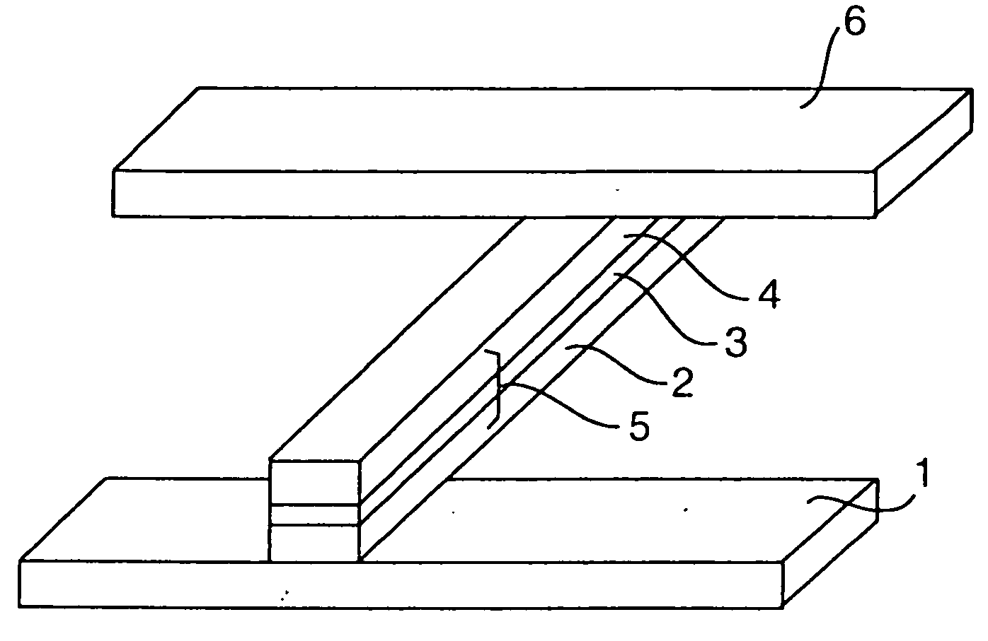
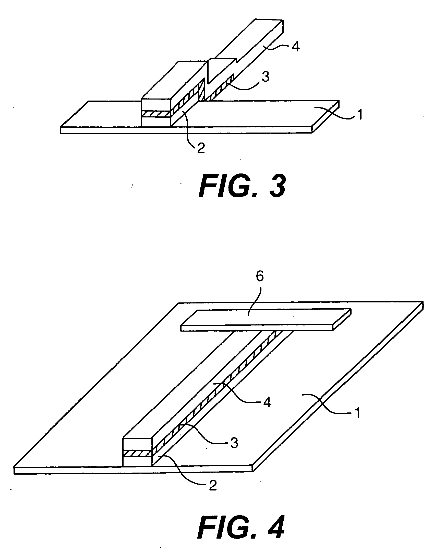
[0078]FIG. 3 shows the structure of a magnetoresistance effect element of the invention.

first embodiment

[0079] The magnetoresistance effect element having the structure shown in FIG. 3 will be described in the same way as in the The process for this magnetoresistance effect element will also be described below. First, the Fe-1.3 at % Ru alloy layer 2 of 5-μm width, 8-μm length and 100-nm thickness is formed on the rectangular Cu electrode 1 of 8-μm width and 2-mm length. Then, the SiO2 layer 3 is deposited to cover all of the Fe-1.3 at % Ru alloy layer 2. Also, the Fe-1.0 at % C alloy layer 4 of 5-μm width, 100-nm thickness is formed to cover all of the SiO2-layer 3. A current is flowed between the Cu electrode 1 and the Fe-1.0 at % C alloy layer 4 and the voltage thereacross is measured.

[0080] In the magnetoresistance effect element shown in FIG. 3, all of the current is flowed in the intermediate layer, and thus the magnetoresistance effect can be effectively utilized. Also, the magnetoresistance effect films can be overlapped in a straight line, and the longitudinal (film surface)...

third embodiment

[0099]FIG. 14 shows the structure of a magnetoresistance effect element of the invention.

[0100] The ferromagnetic spin-dependent tunneling effect film which constitutes the magnetoresistance effect element is formed by an ion beam sputtering apparatus under the following conditions:

Ion gasArAr gas pressure within the2.5 × 10−2 PaapparatusAcceleration voltage of ion gun1200 Vfor evaporationIon current from ion gun for 120 mAevaporationDistance between target and 127 mmsubstrates

[0101] Corning-7059 glass was used for the substrate. The ferromagnetic tunneling effect film in this embodiment was produced by forming on a substrate 31 of a 100-nm thick lower magnetic layer 32 of Fe-1.0 at % C alloy, a 10-nm thick intermediate layer 33 of Al2O3, a 100-nm upper magnetic layer 34 of Fe-1.0 at % C alloy, and a 50-nm thick antiferromagnetic layer 35 of Cr in turn.

[0102] The magnetization curve of the ferromagnetic tunneling effect film was measured at a temperature of 4.2 K by a B-H curve t...


PUM

PropertyMeasurementUnit
coercive forceaaaaaaaaaa
magnetizationaaaaaaaaaa

Abstract

The magnetoresistance effect element is of a multilayered structure having at least magnetic layers and an intermediate layer of an insulating material, a semiconductor or an antiferromagnetic material against the magnetic layers, and the magnetoresistance effect element has terminals formed at least on the opposite magnetic layers, respectively, so that a current flows in the intermediate layer. The film surfaces of all the magnetic layers constituting the magnetoresistance effect element are opposed substantially at right angles to the recording surface of a magnetic recording medium. Therefore, the area of the magnetic layers facing the recording surface of the magnetic recording medium can be extremely reduced, and thus the magnetic field from a very narrow region of the high-density recorded magnetic recording medium can be detected by the current which has a tunneling characteristic and passes through the intermediate layer.

Description

BACKGROUND OF THE INVENTION [0001] This is a continuation application of U.S. Ser. No. 10 / 700,500, filed Nov. 5, 2003; which is a continuation of 10 / 270,120, filed Oct. 15, 2002, now U.S. Pat. Ser. No. 6,687,099; which is a continuation of 09 / 931,897, filed Aug. 20, 2001, now U.S. Pat. Ser. No. 6,483,677; which is a continuation of 09 / 468,309, filed Dec. 21, 1999, now U.S. Pat. Ser. No. 6,278,593; which is a continuation application of 08 / 626,333, filed Apr. 2, 1996, now U.S. Pat. Ser. No. 6,011,674; which is a continuation of 08 / 328,090, filed Oct. 24, 1994, now U.S. Pat. Ser. No. 5,726,837; which is a continuation of 07 / 710,775, filed Jun. 5, 1991, now U.S. Pat. Ser. No. 5,390,061.[0002] This invention relates to magnetoresistance effect elements using a multilayered magnetic thin film with high magnetoresistance effect, and particularly to magnetoresistance effect elements, magnetic heads and magnetic storage apparatus for achieving high-density recording on a magnetic recording ...

Claims


Application Information

Patent Timeline
Patent Type & Authority Applications(United States)
IPC IPC(8): G11B5/33G01R33/09G11B5/39H01F10/32H01L43/08
CPCB82Y10/00Y10T29/49032G01R33/093G11B5/3903G11B5/3909G11B5/3929G11B5/3967G11B5/398G11B2005/0002G11B2005/0016G11B2005/3996H01F10/324H01F10/3254H01F10/3268H01L43/08Y10T29/49044Y10T29/49155Y10T29/49043B82Y25/00H10N50/10
Inventor NAKATANI, RYOICHIKITADA, MASAHIROKOYAMA, NAOKIYUITO, ISAMUTAKANO, HISASHIMORIWAKI, EIJINSUZUKI, MIKIOFUTAMOTO, MASAAKIKUGIYA, FUMIOMATSUDA, YOSHIBUMISHIIKI, KAZUOMIYAMURA, YOSHINORIAKAGI, KYONAKAO, TAKESHIFUKUOKA, HIROTSUGUMUNEMOTO, TAKAYUKITAKAGAKI, TOKUHOKOBAYASHI, TOSHIOTANABE, HIDEOSHIMIZU, NOBORU
Owner HITACHI GLOBAL STORAGE TECH NETHERLANDS BV
Why Eureka
Try Eureka