Interferometric imaging with reduced aperture

a technology of interferometric imaging and aperture reduction, which is applied in the field of imaging systems, can solve the problems of inability of such systems to reproduce a perfect image, degradation of the performance of coherent imaging systems, and increase in the size of the aperture of a lens or primary parabolic mirror, etc., and achieve the effect of enhancing the resolution of optical imaging systems

Inactive Publication Date: 2006-07-13
FARAH JOHN
View PDF1 Cites 24 Cited by
  • Summary
  • Abstract
  • Description
  • Claims
  • Application Information

AI Technical Summary

Benefits of technology

[0020] This invention concerns enhancing the resolution of optical imaging systems.

Problems solved by technology

The failure of such systems to reproduce a perfect image is mainly due to the inability to capture the high frequencies, besides imperfections in the quality of the optical surfaces.
The absence of the high frequency waves in finite aperture imaging systems creates artifacts in the image plane, which account for the degradation of the performance of coherent imaging systems.
An increase in the size of the aperture of a lens or primary parabolic mirror is impractical beyond a certain limit because the cost of fabrication of large focusing elements to optical tolerances becomes prohibitive.
The focused image is susceptible to atmospheric aberrations and to imperfections of the optical surface.
This requires bigger apertures, which increase the cost of the system significantly.
Thus, synthetic aperture techniques inevitably involve computation in a two step process.
This adds delay in the processing of the image, which becomes a concern especially for moving targets.
Thus, the degradation in the visibility of the fringes is due to the lack of perfect coherence due to the diffraction from the pinholes of all the incident waves.
It would be impractical and prohibitively expensive to construct a curved mirror or lens of this diameter out of a monolithic piece of glass while maintaining a high quality optical surface.
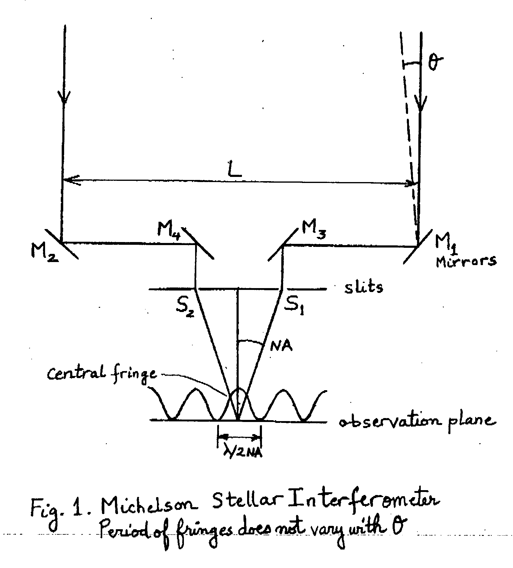
However, Michelson did not produce a complete imaging system.
Thus, it would be impractical to image distant or space objects holographically because the image would be located far away in space in the opposite direction from the object.
The synthetic aperture technique does not resolve the issue of magnification either without prior knowledge of the size of the object or its distance.
But it is not possible to relate the measurement to a specific spatial frequency component or angle of diffraction unless the distance to the object is known.
In the coherent case it is not possible to identify the central fringe because all the fringes have equal visibility, and therefore it is not possible to determine the exact magnification.
However, this does not yield a direct measurement of the spatial components of the irradiance function of the object.
However, in an afocal system, which does not use a lens there is no unique image plane.
The synthetic aperture technique does not measure the phase difference between two non-conjugate orders.
Thus, the synthetic aperture technique does not measure the amplitude and phase as a function of the angle of diffraction and second, measurement of the complex visibility does not yield enough phase relationships among the diffracted orders to permit computation of the inverse Fourier Transform.

Method used


Image

  • Interferometric imaging with reduced aperture
  • Interferometric imaging with reduced aperture
  • Interferometric imaging with reduced aperture

Examples


example 1

[0057] As an example the parameters ƒ1, ƒ2, X1, and L1 are chosen as follows: ƒ1=ƒ2=ƒ, X1=0.828ƒ, and L1=0.414ƒ, where ƒ is an arbitrary number, which provides a length scale of the interferometer. Then we obtain L2=0.417ƒ, dθ2 / dθ1=1.828, and L2dθ2=1.841L1dθ1. Thus, L2dθ2−L1dθ1=0.841L1dθ1.

example 2

[0058] As another example the parameters are chosen as ƒ1=ƒ2=ƒ, X1=ƒ and L1=ƒ. This yields L2=0.914ƒ, dθ2 / dθ1=1.656, and L2dθ2=1.514L1dθ1. Thus, L2dθ2−L1dθ1=0.514L1dθ1.

[0059] These examples demonstrate that it is possible for the phase to retain angular sensitivity even when the two beams A1 and B1 are merged into a single wavefront C, whose cross-section is much narrower than the distance L1 between A1 and B1. The incident wavefront C is split internally to create the two beams A1 and B1. Beams A2 and B2 set up a system of spatial fringes in the vicinity of mirror M9, which picks up the phase at its location and recombines the beams. The results of Examples 1 and 2 indicate that the phase angular sensitivity L2dθ2−L1dθ1 varies with the offset X1 between the incident beam A1 and the optical axis E1. This is due to the variation of the spatial frequency of the fringes with the angle of incidence. Thus, a different angular sensitivity is obtained by moving mirror M9 to a different lo...

example

[0099] An aperture of 1 meter provides an angular resolution of 5×10⁻⁷ radian at a wavelength of 500 nanometers. The corresponding spectral resolution is 10-11 meter or 0.1 Angstrom for a fringe period of about 20 μm compatible with current CCD pixel fabrication technology. This could accommodate 100 channels per nanometer of bandwidth, which is adequate for multi-spectral and hyper-spectral imaging applications.


PUM

PropertyMeasurementUnit
diametersaaaaaaaaaa
angleaaaaaaaaaa
wavelengthaaaaaaaaaa

Abstract

This invention concerns enhancing the resolution of optical imaging systems.

Description

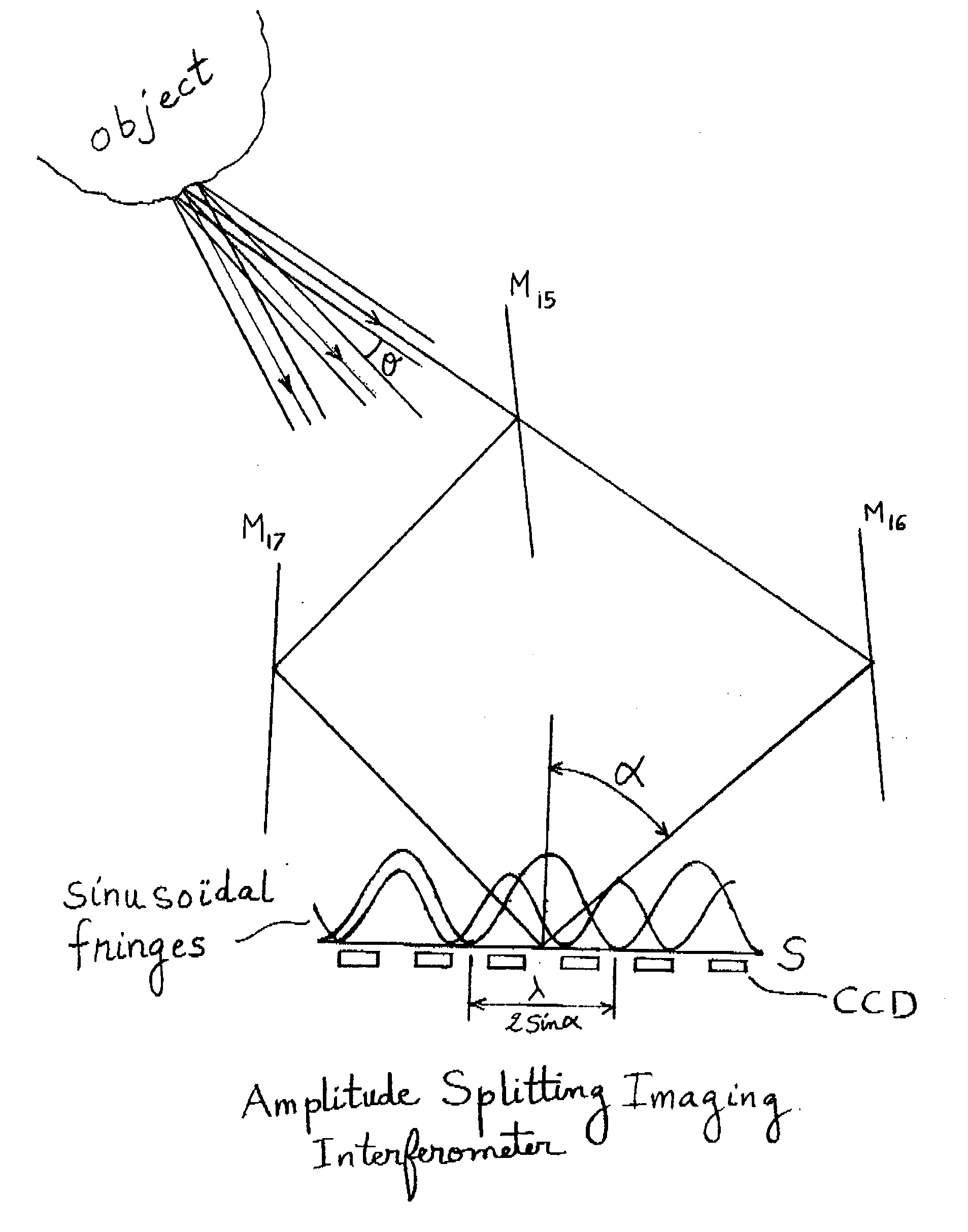
RELATED APPLICATIONS [0001] This application claims priority under 35 U.S.C.§ 119(e) to U.S. Provisional Application Ser. No. 60 / 643,327, entitled “Interferometric Imaging With Reduced Aperture,” filed on Jan. 12, 2005, which is herein incorporated by reference in its entirety.BACKGROUND OF INVENTION [0002] There are two kinds of imaging systems, those that form an image directly and those that synthesize the image from its Fourier components. When an object is illuminated with electromagnetic radiation it creates a diffraction pattern. If the radiation is spatially coherent, then the diffraction consists of a summation of plane waves diverging away from the object each representing one spatial frequency component of the electric field distribution on the object. The angle of diffraction of a particular wave is equal to the spatial frequency times the wavelength of light. Each one of these waves has amplitude and phase associated with it. On a screen in the far field, the diffractio...

Claims


Application Information

Patent Timeline
Patent Type & Authority Applications(United States)
IPC IPC(8): G03B27/42G03F1/00
CPCG01B11/00G01B9/02032G01B2290/10G01B9/02041G01B9/02098
Inventor FARAH, JOHN
Owner FARAH JOHN
Why Eureka
Try Eureka