Processing apparatus and processing method

a technology of processing apparatus and processing method, which is applied in the direction of coating, chemical vapor deposition coating, metallic material coating process, etc., can solve the problems of long evacuation time, inefficient evacuation by dry pump, and long entire process time, so as to reduce the volume of the process chamber, reduce the amount of source gas remaining in the process chamber, and short time

Inactive Publication Date: 2006-07-13
TOKYO ELECTRON LTD
View PDF17 Cites 10 Cited by
  • Summary
  • Abstract
  • Description
  • Claims
  • Application Information

AI Technical Summary

Benefits of technology

[0019] According to the above-mentioned present invention, since evacuation of the source gas is performed by the purge by the inert gas, there is no need to provide a large diameter exhaust port, which is required for acquiring a high-vacuum, to the process chamber, thereby reducing the volume of the process chamber. Therefore, an amount of the source gas remaining in the process chamber can be reduced, which enables the evacuation being performed in a short time.
[0020] Moreover, since the pressure in the process chamber is always maintained constant by supplying also the purge gas when supplying the source gas, the thermal conductivity of the process gas in the process chamber is maintained constant. Therefore, heating of the substrate ...

Problems solved by technology

With such a high degree of vacuum, the flow of gas is in a range of molecular flow, and it is inefficient to evacuate by a dry pump or is it not possible to achieve such a vacuum sorely by a dry pump.
However, enlarging the opening of the exhaust port causes substantially enlarging the process chamber, and there is a problem in that a time required for evacuation is long.
If the process pressure is relatively high pressure, the waiting time for pressure adjustment gives great influence to the process time, which causes the entire process time to become long.
Moreover, when evacuating gas until a high-vacuum is formed in a process chamber, since a source gas, which h...

Method used


Image

  • Processing apparatus and processing method
  • Processing apparatus and processing method
  • Processing apparatus and processing method

Examples


Embodiment Construction

[0026] A description will now be given of a mode of carrying out the present invention.

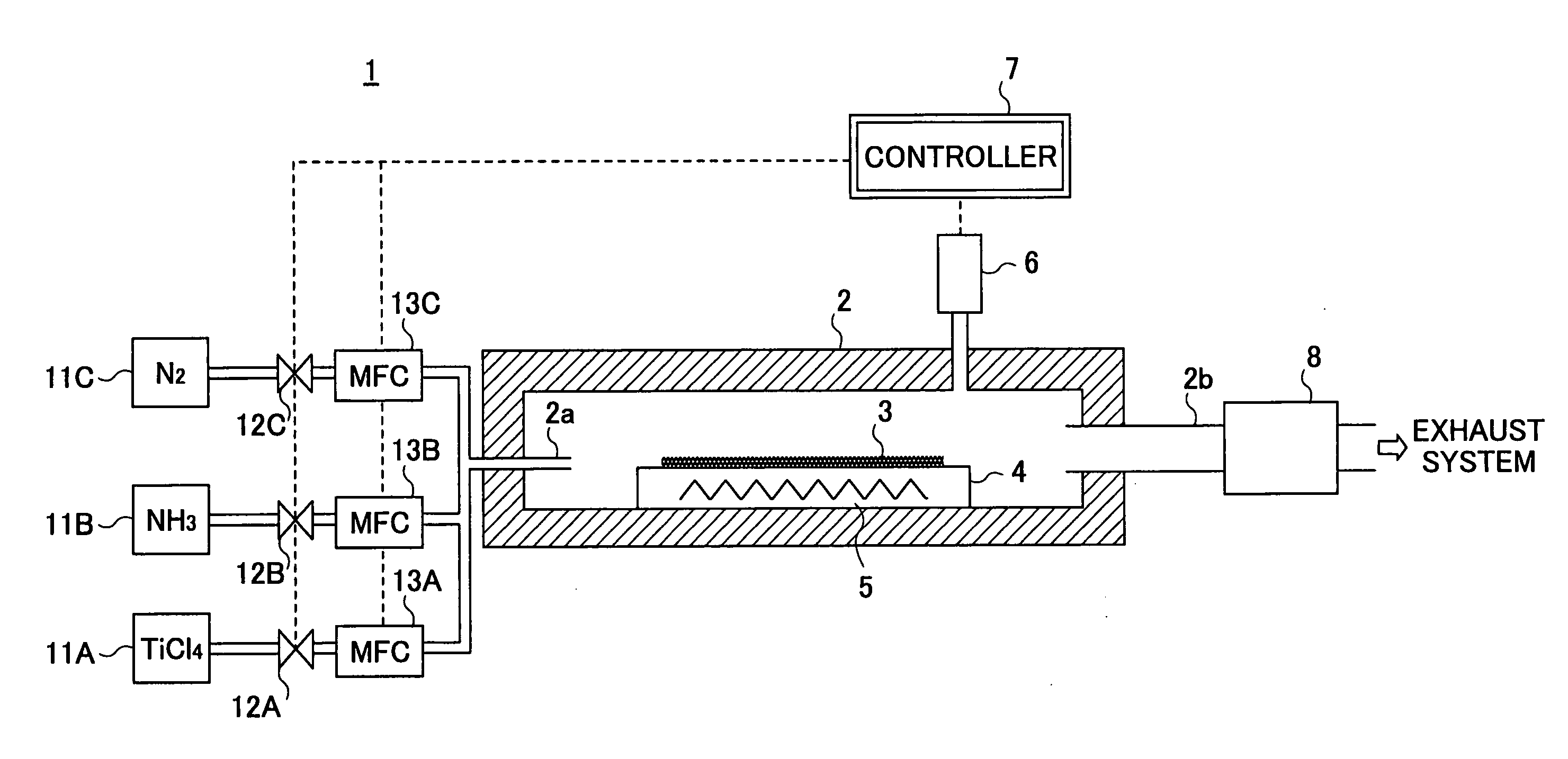
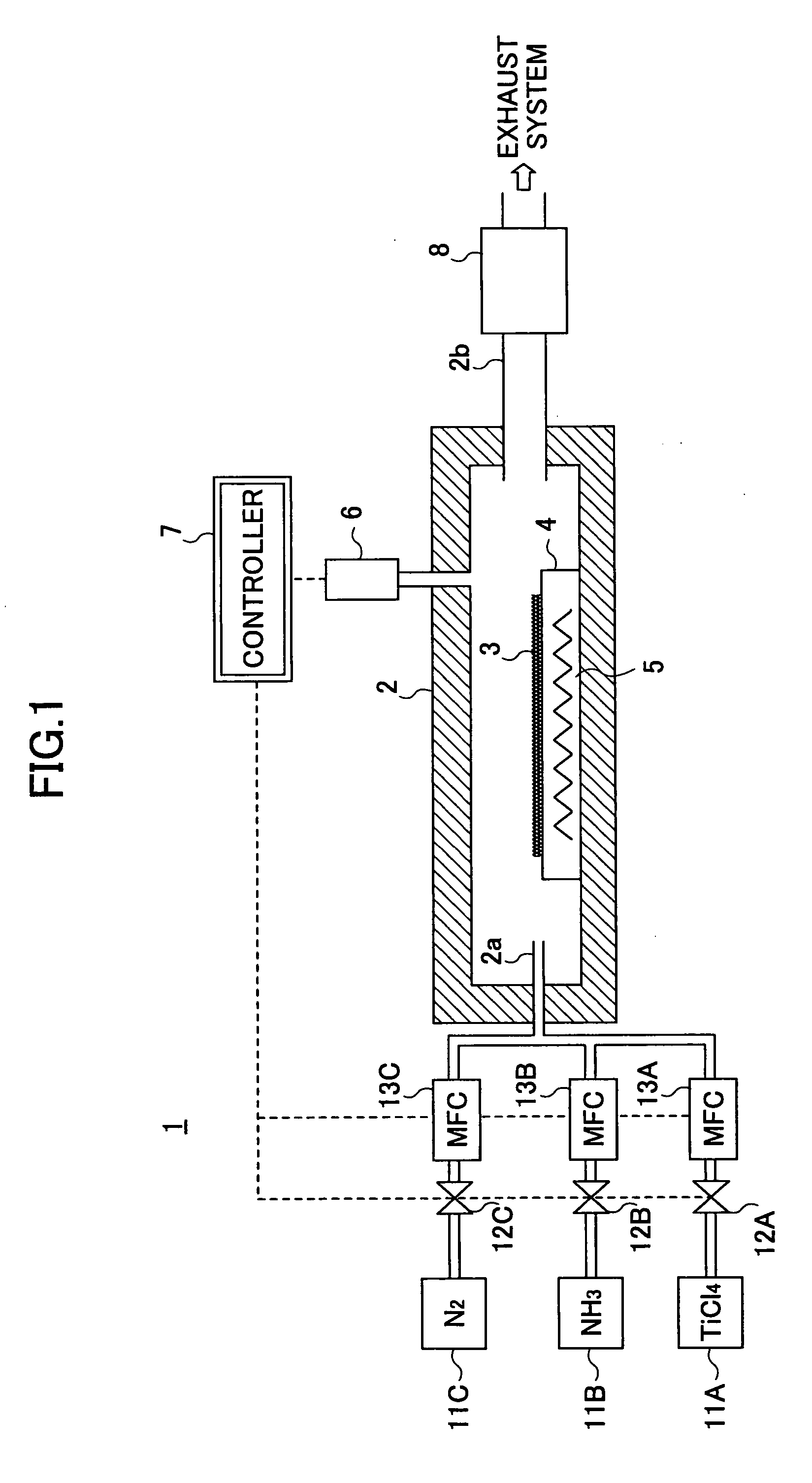
[0027]FIG. 1 is an illustrative structural diagram showing an entire structure of a processing apparatus according to a mode for carrying out the present invention. The processing apparatus 1 shown in FIG. 1 is a processing apparatus for forming a TiN film on a surface of a substrate to be processed by alternately supplying TiCl4 and NH3, as source gases, to the substrate to be processed under a reduced pressure. When supplying the source gasses to the substrate to be processed, the substrate to be processed is heated so as to promote a reaction of the source gases.

[0028] The processing apparatus 1 has a process chamber 2, and a susceptor 4 is arranged in the process chamber 2 as a placement stage on which a wafer 3 as the substrate to be processed is placed. The process chamber 2 is formed of a stainless steel, aluminum, etc., and a process space is formed therein. When the process chamber 2 is...


PUM

PropertyMeasurementUnit
Fractionaaaaaaaaaa
Pressureaaaaaaaaaa
Flow rateaaaaaaaaaa

Abstract

In a processing apparatus, a process gas including a source gas (TiCl4, NH3) and an inert gas (N2) is supplied into a process chamber (2). A pressure meter (6) detects a pressure in the process chamber (2) so as to control an amount of flow of the process gas supplied to the process chamber (2) based on a result of the detection. A source gas is purged by the inert gas. By maintaining the amount of flow of the source gas constant and controlling the amount of flow of the inert gas, an amount of flow the entire process gas is controlled so as to maintain a pressure in the process chamber (2) constant. Since a time spent on evacuation of the source gas is reduced, a time for switching the source gas is reduced. Additionally, a temperature of a surface of a substrate during processing can be maintained constant.

Description

TECHNICAL FIELD [0001] The present invention relates to processing apparatuses and, more particularly, to a processing apparatus and a processing method that perform a process on a substrate in a process chamber while supplying gas to the process chamber. BACKGROUND ART [0002] As a method of processing a substrate of a semiconductor device, a method of processing the substrate by supplying a source gas and purge gas into a process chamber that is maintained at a predetermined degree of vacuum is common. For example, as a method of forming a high-quality thin film on a substrate by supplying process gas to the heated substrate under a reduced pressure, ALD (Atomic Layer Deposition) has attracted attention in recent years. [0003] In ALD, a plurality of kinds of source gases are supplied to a substrate alternately under a pressure of about 200 Pa and caused to react with each other on the substrate that is heated at 400° C. to 500° C. so as to form a very thin film of a reaction produc...

Claims


Application Information

Patent Timeline
IPC IPC(8): H01L21/00C23C16/00C23C16/52C23C16/34C23C16/44C23C16/455H01L21/205H01L21/285H01L21/31
CPCC23C16/34H01L21/28562C23C16/45557H01L21/205
Inventor KANNAN, HIROSHIISHIZAKA, TADAHIROKOJIMA, YASUHIKOOSHIMA, YASUHIROSHIGEOKA, TAKASHI
Owner TOKYO ELECTRON LTD
Why Eureka
Try Eureka