Apparatus and method for deploying an implantable device within the body

a technology of implantable devices and apparatus, applied in the field of vascular disease, can solve the problems of inability to adapt the system to small vessels, cumbersome and difficult to employ and execute, and the difficulty of aligning and interconnecting legs with the lumen with enough precision to avoid leakage, and achieve the effect of evaluating the suitability of the resulting deploymen

Active Publication Date: 2006-07-13
TAHERI LADUCA
View PDF98 Cites 148 Cited by
  • Summary
  • Abstract
  • Description
  • Claims
  • Application Information

AI Technical Summary

Benefits of technology

[0020] An advantage of the stent delivery system of the present invention is that it does not require the use of space-occupying stylets and balloon catheters.
[0021] Another advantage of the subject system is that it allows for adjustment of the position or placement, as well as removal, of a stent during and after deployment thereof.
[0022] The present invention is additionally advantageous in that it provides a user with the ability to deploy a stent, to evaluate the suitability of the resulting deployment using standard imaging, such as by use of radiographic dye and fluoroscopy or any other imaging system, to check for endoleak between the covered stent wall and the surrounding arterial wall and to detach the stent from the delivery system upon adequate stent deployment or, in the case of an inadequate deployment, to either relocate the stent to a new location and obtain a satisfactory result by controlling the delivery and detachment of the stent in a repeatable manner, or to remove the stent entirely.
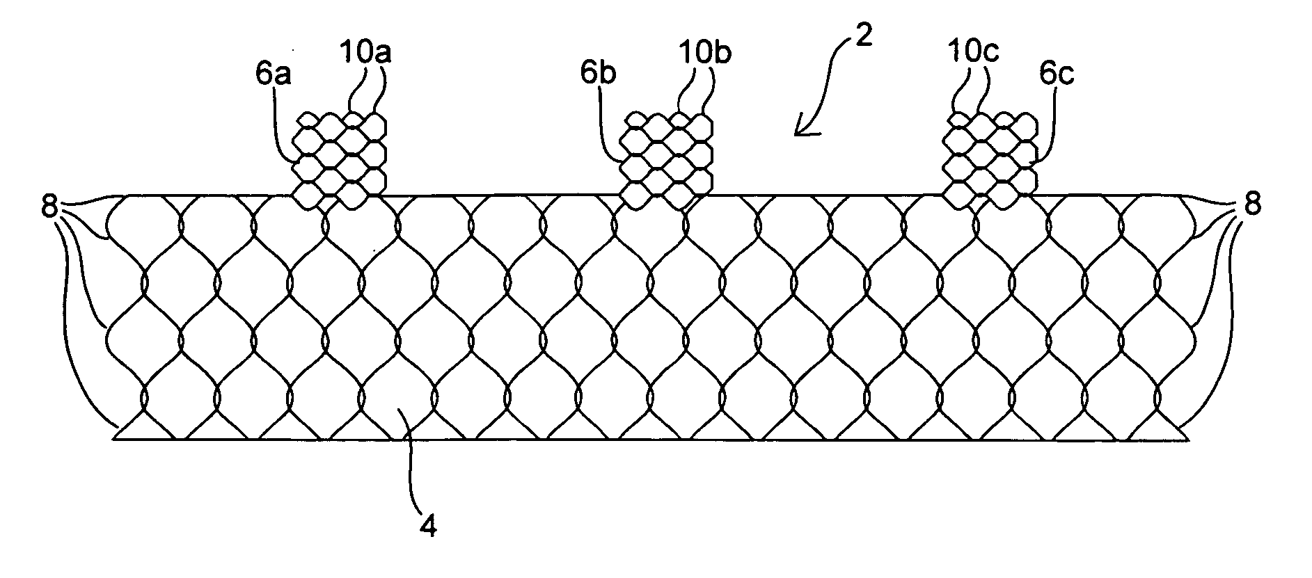
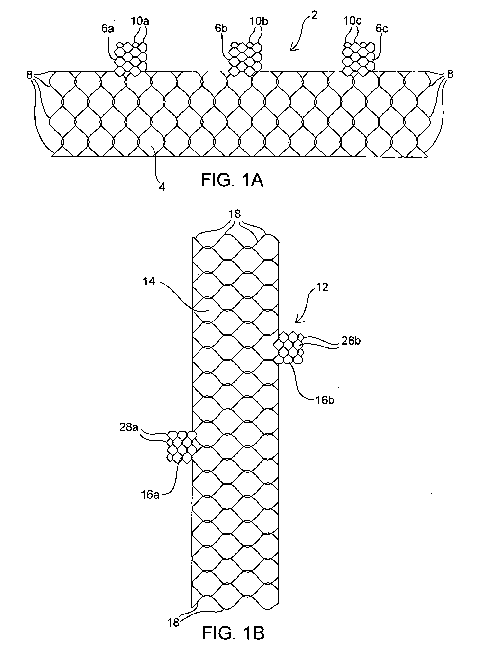
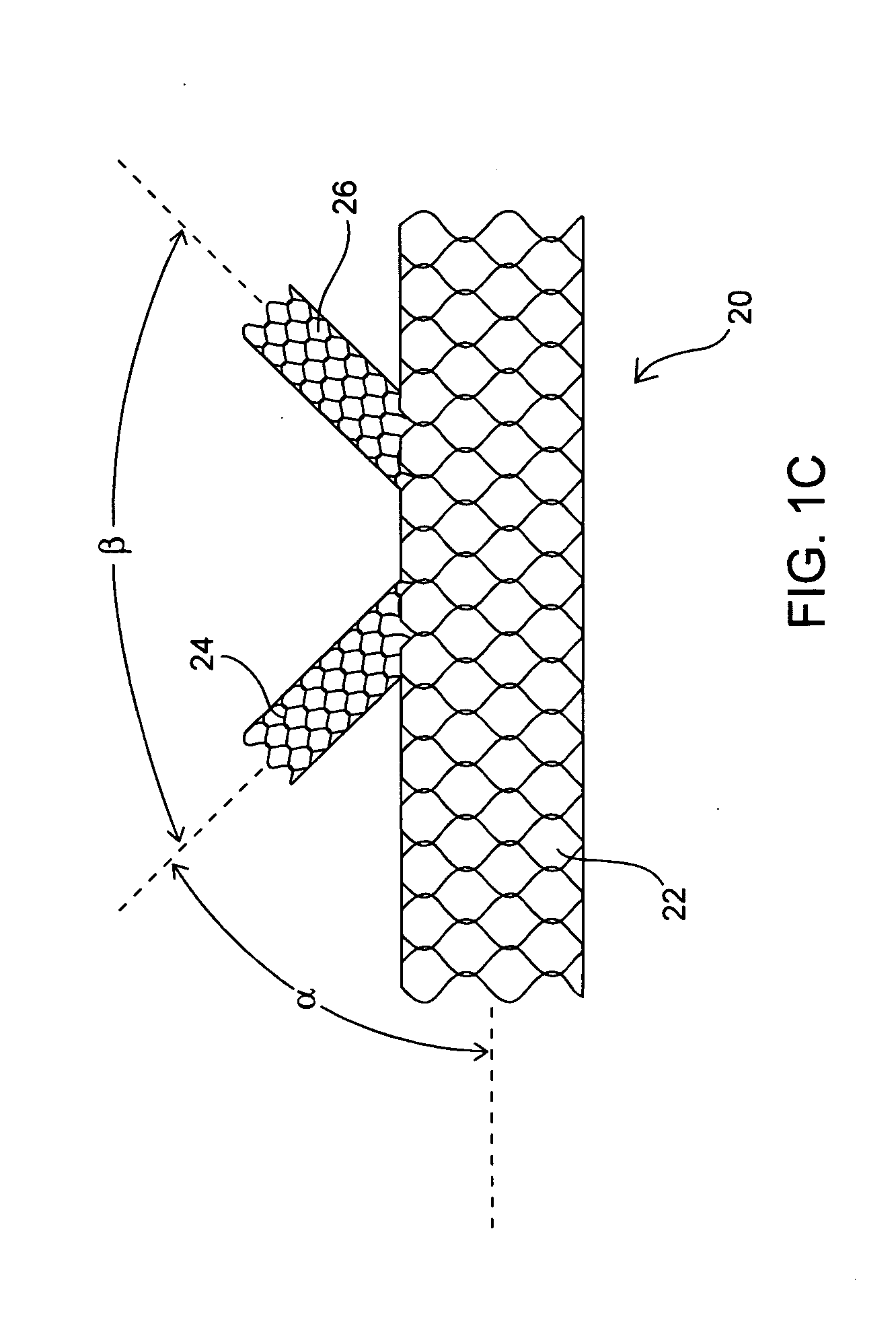
[0023] The present invention is additionally advantageous in that it secures the stent from migration within the vasculature by integrating the cells of the side branch lumen into the cells of the main body lumen such that, when the side branch lumens are deployed within their branch vessels, the main body lumen is constrained from migration by a “lock and key” mechanism. More specifically, the interconnection of the side branch lumen to the main body lumen is accomplished by forming the side branch lumen and the main body lumen from the same single wire where a specific wire wrap pattern is used to form a linking mesh to integrate the side branch lumen with the main lumen. Thus, when the side branch is deployed within and held in place by the side branch artery, the main body of the stent cannot migrate. Moreover, such a “passive” anchoring mechanism is atraumatic, as opposed to an active anchoring means, such as barbs or hooks, which may damage the cellular structures of the implant site leading to smooth muscle proliferation, restenosis, and other vascular complications.

Problems solved by technology

A more challenging situation occurs when it is desirable to use a stent, a graft or a stent graft at or around the intersection between a major artery (e.g., the abdominal aorta) and one or more intersecting arteries (e.g., the renal arteries).
Additionally, a plurality of stylets is necessary to deliver the graft, occupying space within the vasculature and thereby making the system less adaptable for implantation into smaller vessels.
These techniques, while effective, may be cumbersome and somewhat difficult to employ and execute, particularly where the implant site involves two or more vessels intersecting the primary vessel, all of which require engrafting.
Although the delivery of modular systems is less difficult due to the smaller sizes of the components, it is difficult to align and interconnect the legs with the body lumen with enough precision to avoid any leakage.
On the other hand, while unitary stents reduce the probability of leakage, their larger structure is often difficult to deliver to a treatment site having a constrained geometry.
While the conventional bifurcated stents have been used somewhat successfully in treating AAAs, they are not adaptable where the implant site is within the aortic arch.
The arch region of the aorta is subject to very high blood flow and pressures which make it difficult to position a stent graft without stopping the heart and placing the patient on cardiopulmonary bypass.
As such, if an aortic arch graft is not able to expand and contract to accommodate such changes, there may be an insufficient seal between the graft and the aortic wall, subjecting it to a risk of migration and / or leakage.
Further, the complexity (e.g., highly curved) and variability of the anatomy of the aortic arch from person to person makes it a difficult location in which to place a stent graft.
However, while such measurements and the associated manufacture of such a custom stent could be accomplished, it would be time consuming and expensive.
Furthermore, for those patients who require immediate intervention involving the use of a stent, such a customized stent is impractical.
Another disadvantage of conventional stents and stent grafts is the limitations in adjusting the position of or subsequently retrieving the stent or stent-graft once it has been deployed.
Often, while the stent is being deployed, the final location of the delivered stent is determined not to be optimal for achieving the desired therapeutic effect.
While this self-expanding capability is advantageous in deploying the stent, it presents the user with a disadvantage when desiring to remove or reposition the stent.
The limitation of this design is the lack of ability to reduce the diameter of the entire length of stent by stretching the stent which is pursed down on the distal end by the trigger wire.
Another disadvantage of conventional stent-grafts is the temporary disruption in blood flow through the vessel.
In the case of balloon deployable stents and stent-grafts, expansion of the balloon itself while deploying the stent or stent-graft causes disruption of blood flow through the vessel.
In the case of self-expanding stent-grafts, the misplacement of a stent graft may be due to disruption of the arterial flow during deployment, requiring the placement of an additional stent-graft in an overlapping fashion to complete the repair of the vessel.
While the use of attached strings provides some additional control of the stent's placement, one skilled in the art can appreciate that passing strings from within the vasculature through a second opening presents procedural difficulties.

Method used


Image

  • Apparatus and method for deploying an implantable device within the body
  • Apparatus and method for deploying an implantable device within the body
  • Apparatus and method for deploying an implantable device within the body

Examples


Embodiment Construction

[0041] Before the devices, systems and methods of the present invention are described, it is to be understood that this invention is not limited to particular therapeutic applications and implant sites described, as such may vary. It is also to be understood that the terminology used herein is for the purpose of describing particular embodiments only, and is not intended to be limiting, since the scope of the present invention will be limited only by the appended claims.

[0042] Unless defined otherwise, all technical and scientific terms used herein have the same meaning as commonly understood by one of ordinary skill in the art to which this invention belongs. The terms “proximal” and “distal” when used to refer to the delivery and deployment systems of the present invention are to be understood to indicate positions or locations relative to the user where proximal refers to a position or location closer to the user and distal refers to a position or location farther away from the ...


PUM


Abstract

The present invention provides devices and methods for fabricating and deploying an implantable device within the body. The invention is particularly suitable for delivering and deploying a stent, graft or stent graft device within a vessel or tubular structure within the body, particularly where the implant site involves two or more interconnecting vessels. The delivery and deployment system utilizes a plurality of strings which are releasably attached to the luminal ends of the implantable device.

Description

CROSS-REFERENCE TO RELATED APPLICATIONS [0001] This application is a continuation-in-part of U.S. patent application Ser. No. 11 / 033,479 filed on Jan. 10, 2005, incorporated herein in its entirety.FIELD OF THE INVENTION [0002] The present invention relates to the treatment of vascular disease, including for example aneurysms, ruptures, psuedoaneurysms, dissections, exclusion of vulnerable plaque and treatment of occlusive conditions, and more particularly, the invention is related to an apparatus and method for delivering and deploying an implantable device within the body to treat such conditions. The present invention is particularly suitable for implanting stents, grafts and stent grafts within arteries or other vessels at sites involving two or more intersecting vessels. BACKGROUND OF THE INVENTION [0003] It is well known in the prior art to treat vascular disease with implantable stents and grafts. For example, it is well known in the art to interpose within a stenotic or occlu...

Claims


Application Information

Patent Timeline
Patent Type & Authority Applications(United States)
IPC IPC(8): A61F2/06A61F2/90
CPCA61F2/2418A61F2220/0066A61F2/90A61F2/95A61F2/954A61F2002/075A61F2002/9511A61F2002/9517A61F2250/0039A61F2/06A61F2220/0016A61F2220/0075A61F2220/0008A61F2220/0041A61F2/856A61F2/9517A61F2/844
Inventor LADUCA, ROBERTLADUCA, PAUL
Owner TAHERI LADUCA
Why Eureka
Try Eureka