Digital signal processing back biased hall effect muzzle velocity measurement system

a digital signal processing and measurement system technology, applied in the field of measuring systems, can solve the problems of not providing an actual point of exit measurement, optical and fiber optic systems are not suitable for combat environment, and are not practical for fielding, etc., to achieve the effect of low power consumption, minimal power consumption and simple mounting design

Inactive Publication Date: 2006-07-20
HONEYWELL INT INC
View PDF12 Cites 20 Cited by
  • Summary
  • Abstract
  • Description
  • Claims
  • Application Information

AI Technical Summary

Benefits of technology

[0015] A primary advantage of the present invention is that by having the muzzle velocity system on board the weapon, no special provisions need to be made to ensure the muzzle velocity system is pointed along the path of the projectile.
[0016] Another advantage of the present invention is the simplicity in the mounting design of the muzzle velocity measurement system on a muzzle.
[0017] Another advantage of the present invention is that due to the low power consumption, the measurement system can be battery operated remotely away from and without attachment from a continuous power supply, such as a battery. This invention is designed to draw minimal power so that the muzzle velocity system will operate for extended lengths of time.

Problems solved by technology

Radar systems presently are used to analyze the ballistic path but do not provide an actual point of exit measurement.
The inductive approach exhibits a characteristic reduced frequency response while optical and fiber optic systems are not suitable to the combat environment or are not practical for fielding.
RF injection requires that the barrel be penetrated at multiple locations which violates the military standard for barrel structural integrity.

Method used


Image

  • Digital signal processing back biased hall effect muzzle velocity measurement system
  • Digital signal processing back biased hall effect muzzle velocity measurement system
  • Digital signal processing back biased hall effect muzzle velocity measurement system

Examples


Embodiment Construction

)

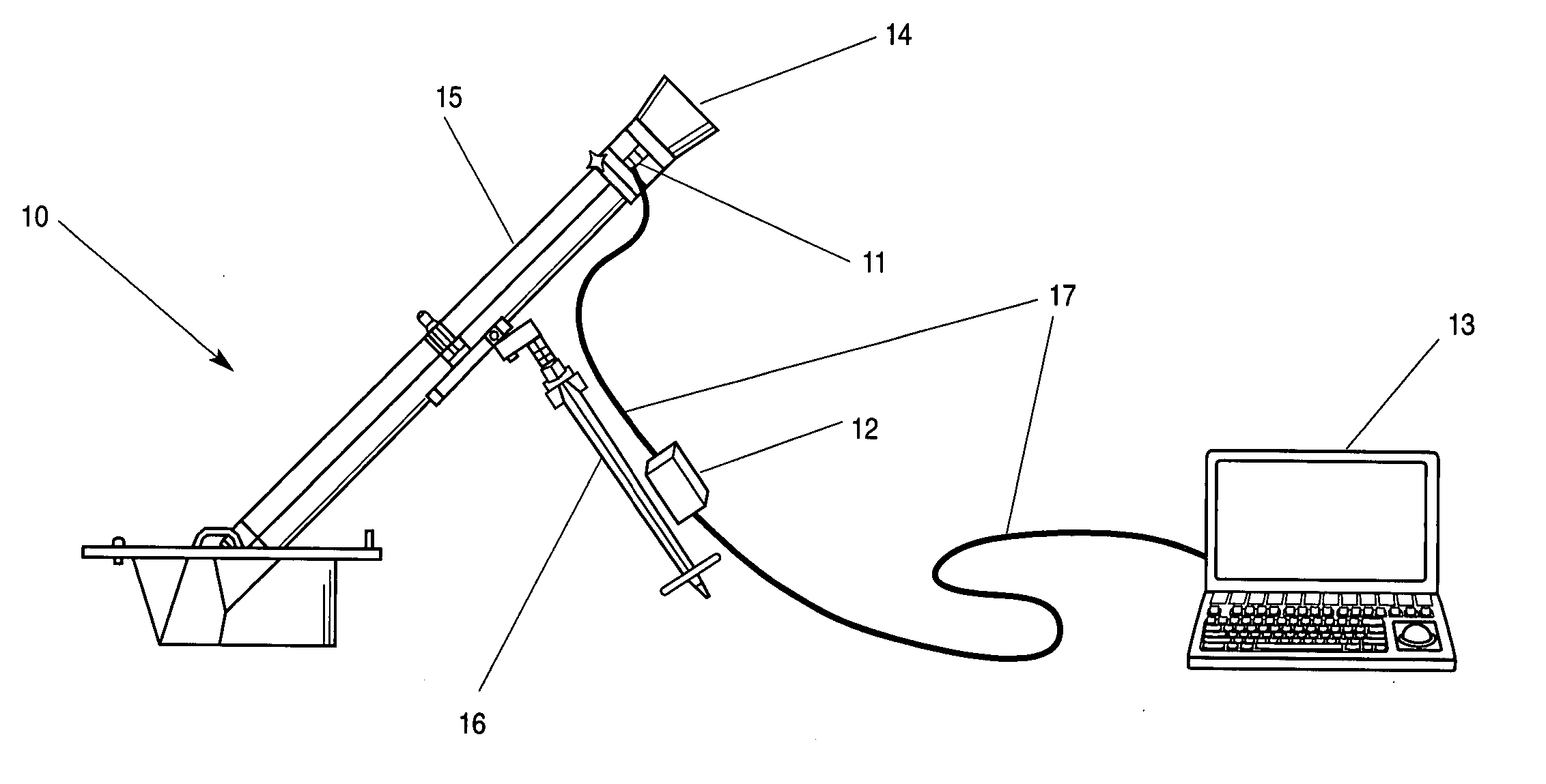
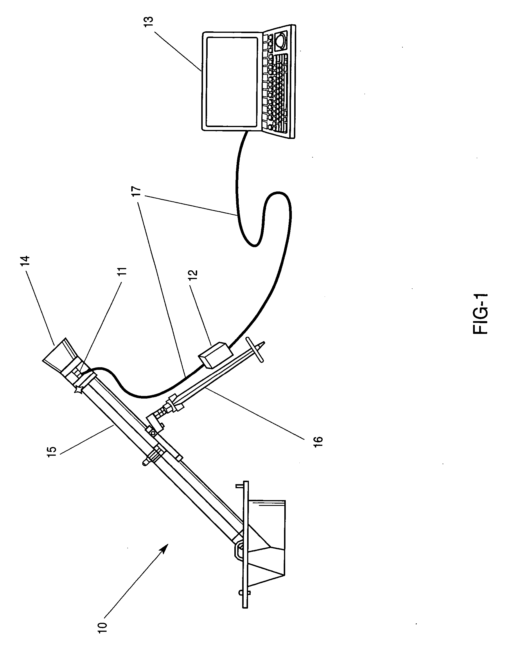
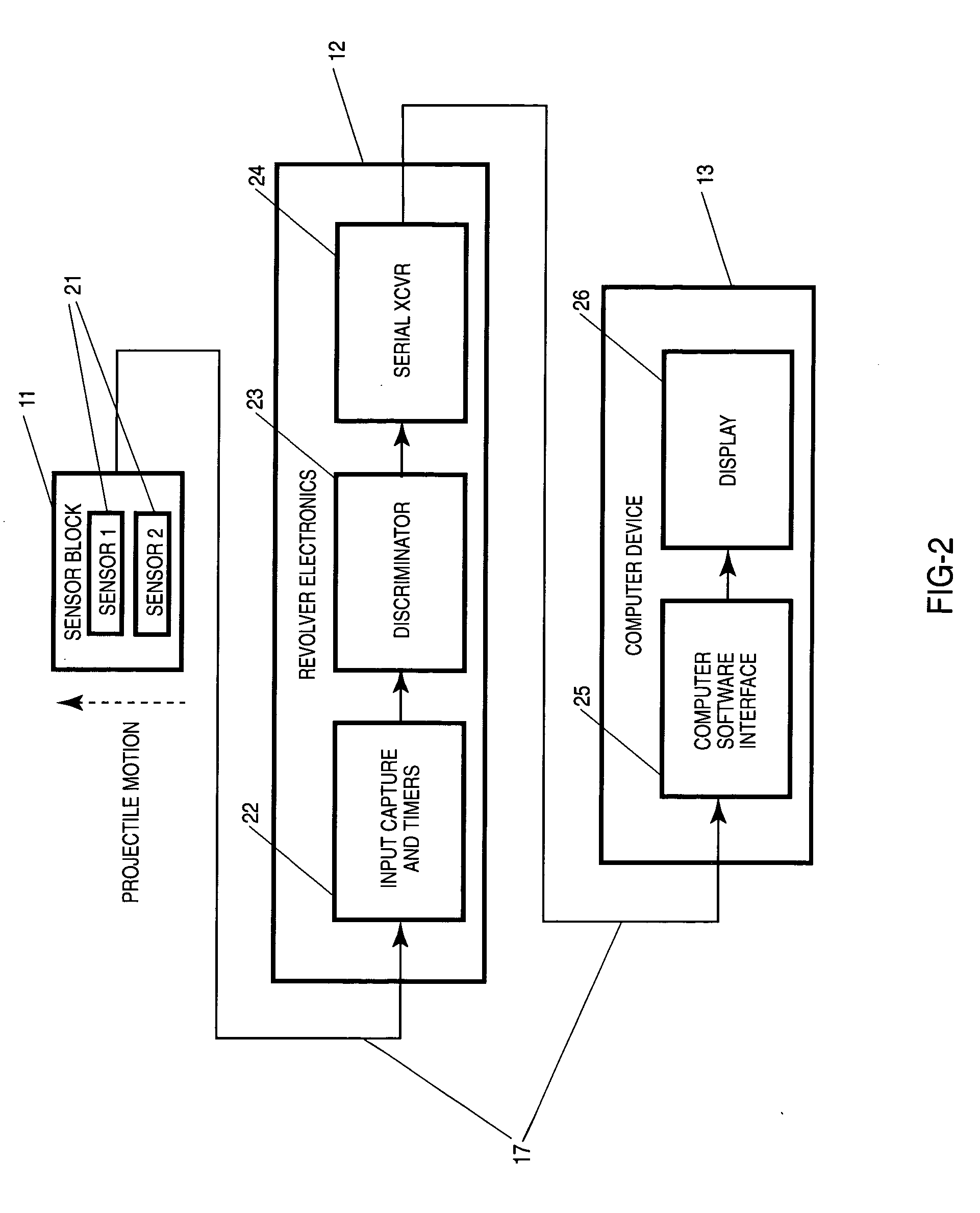
[0032] A unique method and apparatus for accurately measuring the velocity of a mortar projectile is disclosed. FIGS. 1 and 2 show the typical set up for the present invention. Mortar weapon 10 is equipped with a sensor block 11, a digital resolver module 12, and a computing device 13. Sensor block 11 is integrated into a mechanical coupling 14 that is attached to mortar weapon 10 at the exit of cannon 15. In the preferred sensor block 11, two back-biased Hall effect sensors 21 are used, however more sensors could be used for a more accurate measurement. Digital resolver module 12 consists of electronics housed in a mechanical enclosure that is mechanically attached to mortar weapon 10 in an area that provides mechanical isolation from cannon 15, such as either bipod leg 16. Typical electronics for resolver module 12 include input capture and timer electronics 22, discriminator electronics 23, and serial transceiver (XCVR) 24. Computing device 13 is a host for computer software int...


PUM

PropertyMeasurementUnit
frequencyaaaaaaaaaa
speedaaaaaaaaaa
distanceaaaaaaaaaa

Abstract

A system for precisely measuring muzzle exit velocity of a “muzzle loaded” mortar projectile fired from a mortar tube using two back-biased Hall effect sensors for projectile gas ring channel detection. The system includes a back-biased Hall effect sensor block, a digital resolver electronic circuit and a computer software interface. The back-biased Hall effect sensors are located in a calibrated sensor block attached to a mortar tube. As the projectile metal casing passes a face of the sensors, the sensors trigger and release, providing two electronic pulses. The pulse edges are captured in the resolver electronics, containing a discriminator circuit for filtering all input pulses to distinguish between a projectile loading event and a projectile firing event. Once a valid firing event is detected, an output of precision timers is presented serially to a computer where it is processed and displayed by a computer software interface.

Description

GOVERNMENT RIGHTS [0001] The U.S. Government has a paid-up license in this invention and the right in limited circumstances to require the patent owner to license others on reasonable terms as provided for by the terms of DAAE30-03-D-1004, awarded by the Department of the Army.BACKGROUND OF THE INVENTION [0002] 1. Field of the Invention (Technical Field) [0003] The present invention relates to measuring systems and more specifically to a method and apparatus for measuring a mortar muzzle exit velocity. [0004] 2. Background Art [0005] This present invention solves the problem of providing accurate primary instrumentation for the measurement of the velocity of a projectile at the muzzle point of exit. Many variables affect muzzle velocity. Examples include, but are not limited to barrel wear, propellant temperature, unique propellant burn rate, and air density. While some of these variables can accurately be accounted for individually, when taken in total, it is most efficient to simp...

Claims


Application Information

Patent Timeline
Patent Type & Authority Applications(United States)
IPC IPC(8): G01L5/14
CPCF41A21/32F41F1/06G01P3/665
Inventor SHIPMAN, JOHN M.JUDKINS, ERIC T.MARTIN, J. RICKBURKHOLDER, DANIEL E.
Owner HONEYWELL INT INC
Why Eureka
Try Eureka