Rotating tubular sputter target assembly

a technology of sputter and target, which is applied in the direction of diaphragms, electrodes, ion implantation coatings, etc., can solve the problems of affecting the operation of the motor, damage to the target assembly and/or melting of the target material, and the combination of all of them in a single assembly is a technology in its own right, so as to simplify the mounting of the motor and simplify the concep

Inactive Publication Date: 2006-07-20
CNOCKAERT DIRK +1
View PDF4 Cites 38 Cited by
  • Summary
  • Abstract
  • Description
  • Claims
  • Application Information

AI Technical Summary

Benefits of technology

[0045] As a drive means an electrical motor can be used (claim 2). This motor is preferably of the fixed axis, rotating drum type (claim 3), since this simplifies the mounting of the motor.
[0046] As an alternative to

Problems solved by technology

The target assembly has to be cooled because the dense bombardment of the surface leads to an intense heating that would quickly lead to damage of the target assembly and/or melting of the target material.
While each of these functionalities are relatively simple to attain individually, the combination of all of them in a single assembly is a technological problem in its own right.
While these designs made the use of large target tubes practical, the end blocks or the bearing housing have a serious drawback in that they occupy a substantial part of the chamber which cannot longer be used for deposition of material, but anyhow has to be pumped vacuum.
Moreover, they decrease the useable deposit

Method used


Image

  • Rotating tubular sputter target assembly
  • Rotating tubular sputter target assembly
  • Rotating tubular sputter target assembly

Examples


Embodiment Construction

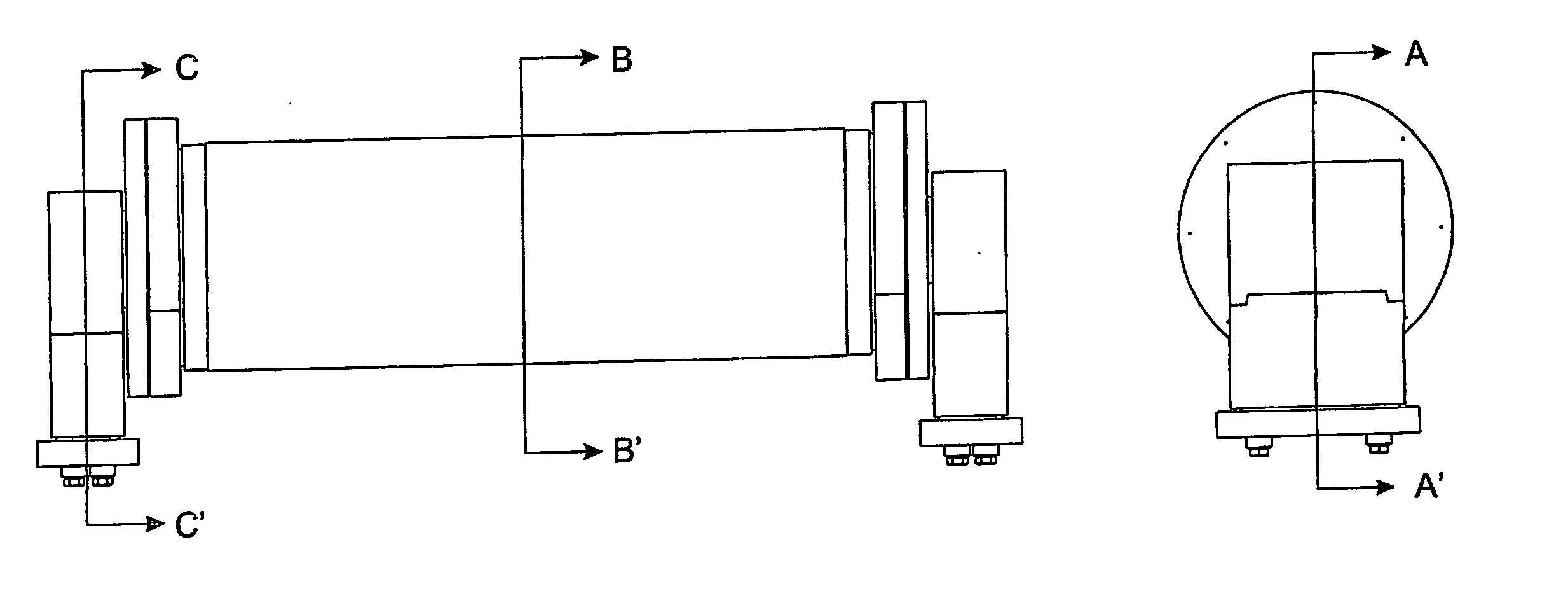
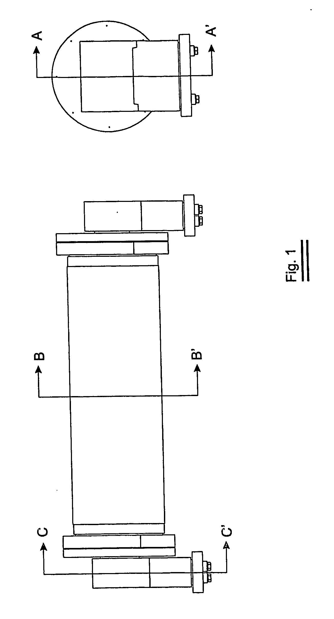
[0060] As the working principle of rotatable target assemblies is generally known in the art, focus will be given to the detailed description of the invention of which a first preferred embodiment is represented in FIG. 1.

[0061] In this embodiment all the functionalities as enumerated in claim 1 are incorporated inside the target tube. The drive means is an electrical motor. The supply and extraction of the coolant and the charging of the surface is through a first coupling means. The electricity to drive the electrical motor is fed through a second coupling means.

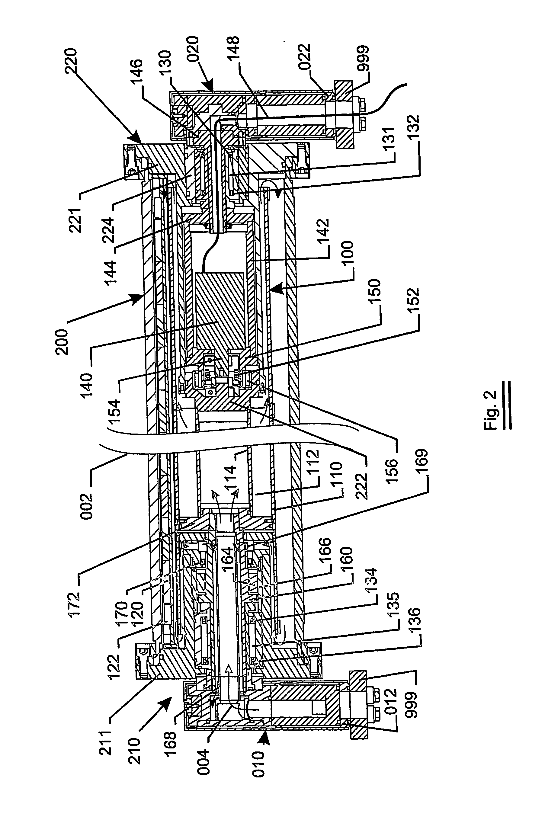
[0062]FIG. 2 shows the carrier tube 100 and the rotating tube 200. The rotating tube 200 can be made of the target material itself e.g. aluminium tube. Or the target material can be disposed at the outside of the rotating tube. It can be applied onto the tube 200 by means of thermal plasma torch spraying, or by electrolytic deposition, or by any other technique known in the art. The total length of the tube can be chosen...


PUM

PropertyMeasurementUnit
Volumeaaaaaaaaaa

Abstract

A target assembly is claimed for use in e.g. a magnetron deposition apparatus. The target assembly is characterised in that at least one of the functions—bearing of the tube, rotation of the tube, electrical contact, coolant sealing and vacuum sealing—is integrated into the tube itself. Such an assembly has the advantage that it better uses the vacuum space by reducing the volume incorporated by the end blocks. Due to the compactness of the assembly it can also be used in smaller scale installations where now only planar target assemblies can be used.

Description

FIELD OF THE INVENTION [0001] The invention relates to a target assembly comprising a central body in a rotatable target tube. BACKGROUND OF THE INVENTION [0002] The use of rotatable targets for large area plasma deposition of thin films onto e.g. window glass has become widespread. Metallic deposition—under an inert gas atmosphere—as well as the deposition of compound materials—when a reactive gas is mixed with the inert gas—are performed on an industrial scale in large sputter deposition installations. One of the key components in this process remains the target assembly, which has to fulfil all of the following functions: [0003] It has to keep the magnetic field source in place. The generated magnetic field at the outside of the tube confines the electrons in a narrow closed loop track leading to an increased ionisation of the inert gas atoms. [0004] The assembly must support the target tube rotatably. [0005] The target surface must be rotated in front of the magnetic field sourc...

Claims


Application Information

Patent Timeline
IPC IPC(8): C23C14/00C23C14/34H01J37/34
CPCH01J37/3435H01J37/3497H01L21/67207H01F7/02F04D17/168C23C14/3407C23C14/35H01L21/02631
Inventor CNOCKAERT, DIRKDE BOSSCHER, WILMERT
Owner CNOCKAERT DIRK
Why Eureka
Try Eureka