Method and apparatus for continuously producing discrete expanded thermoformable materials

Inactive Publication Date: 2006-07-20
PANTERRA ENGINEERED PLASTICS
View PDF16 Cites 6 Cited by
  • Summary
  • Abstract
  • Description
  • Claims
  • Application Information

AI Technical Summary

Benefits of technology

[0023] In another embodiment of the present invention, the raw material selected can contain physical properties, such as low viscoelasticity, that allow for the formation of holes or tears in the side of the formed material. These holes or tears can allow for the passage of materials through the finished material.
[0032] All of the above embodiments can further have a system that can control the combined extrusion and coreforming process, such as by regulating temperature, rate of movement of the materials, buffering or loading of the extruded sheets, expansion of the material, cooling, loading, unloading, or any other aspect of the present invention.

Problems solved by technology

One disadvantage with these processes is that there are large economic losses due to the use of discrete thermopolymer sheets.
The process of expanding the thermopolymer sheet destroys the polish that the sheet had been given during the extrusion process.
There are multiple sources of waste associated with this process, namely the additional manpower and time needed to perform these tasks.
In addition, the cost of production is substantially increased because of the amount of wasted energy in these conventional processes.
Each thermoformable sheet material must be reheated since all of the energy from the original heating of the resin in the extruder is lost.
Thus, the cost of production is increased because energy must be purchased to heat each new sheet of thermoformable material prior to expansion, and all of this energy is wasted during the initial cooling process.
A further disadvantage of the previous methods is that many of the thermoformable materials are hydrophilic and absorb moisture from the air.
First, the moisture will absorb heat and unnecessarily require additional energy to bring the thermoformable material up to expansion temperature.
Secondly, and perhaps more importantly, the moisture in the thermoformable material will expand as it turns to vapor at the thermoforming temperatures resulting in voids, fissures and other defects in the finished expanded honeycomb core product, making it structurally unsound and commercially unacceptable.
This of course is an additional step that requires energy, manpower, time, floor space, additional equipment and ultimately cost.
Furthermore, another disadvantage of the conventional processes described above are that they are neither automated nor continuous from the input of the raw material to the finished product, and typically require multiple manufacturing personnel, multiple heating and cooling stages, and other steps that are necessary to produce one expanded thermoformable product.
Obviously, the use of multiple personnel greatly increases the cost of manufacturing, together with the long product cycle times and energy loss.
Finally, the existing processes have inherent limitations in terms of volume throughput and capacity and the ability to scale-up to meet large customer demands.
All the aforementioned processes are batch processes and cannot deliver volume production yields.
At the same time, the built-in economic and energy disadvantages of these processes make them impractical in meeting the requirement of large scale demand.

Method used


Image

  • Method and apparatus for continuously producing discrete expanded thermoformable materials
  • Method and apparatus for continuously producing discrete expanded thermoformable materials
  • Method and apparatus for continuously producing discrete expanded thermoformable materials

Examples


first embodiment

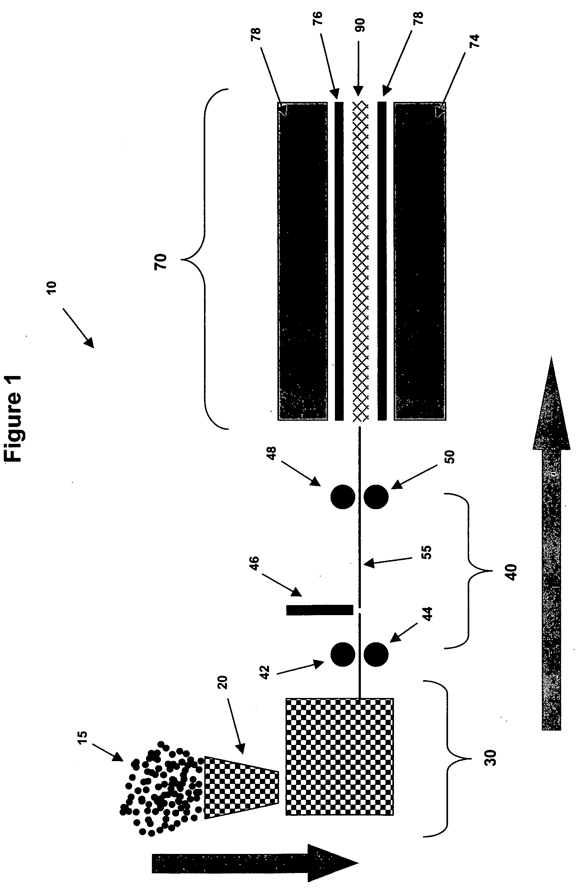
[0039] Referring to FIG. 1, the present invention, generally referred to by reference numeral 10, is shown. System 10 has hopper 20, extruder 30, conveyor system 40, and coreformer or expander 70.

[0040] To begin the process of the claimed invention, thermoplastic raw material 15 is loaded into hopper 20. This material is usually in pellet form. Suitable examples of such material include, but are not limited to, high impact polystyrene, polycarbonate, acrylonitrile butadiene styrene, homo or co-polymer polypropylene, low and high density polyethylene and combinations thereof.

[0041] Hopper 20 then feeds the raw material into extruder 30. These materials can be extruded or molded utilizing unfilled polymers, polymer alloys, fiber / filler / nano reinforced polymers, flexible polymers, recycled polymers or combinations of the above. Inside extruder 30, the raw material is heated to a temperature as high as about 300° C., at which point the material becomes a viscous liquid. In this state, ...

second embodiment

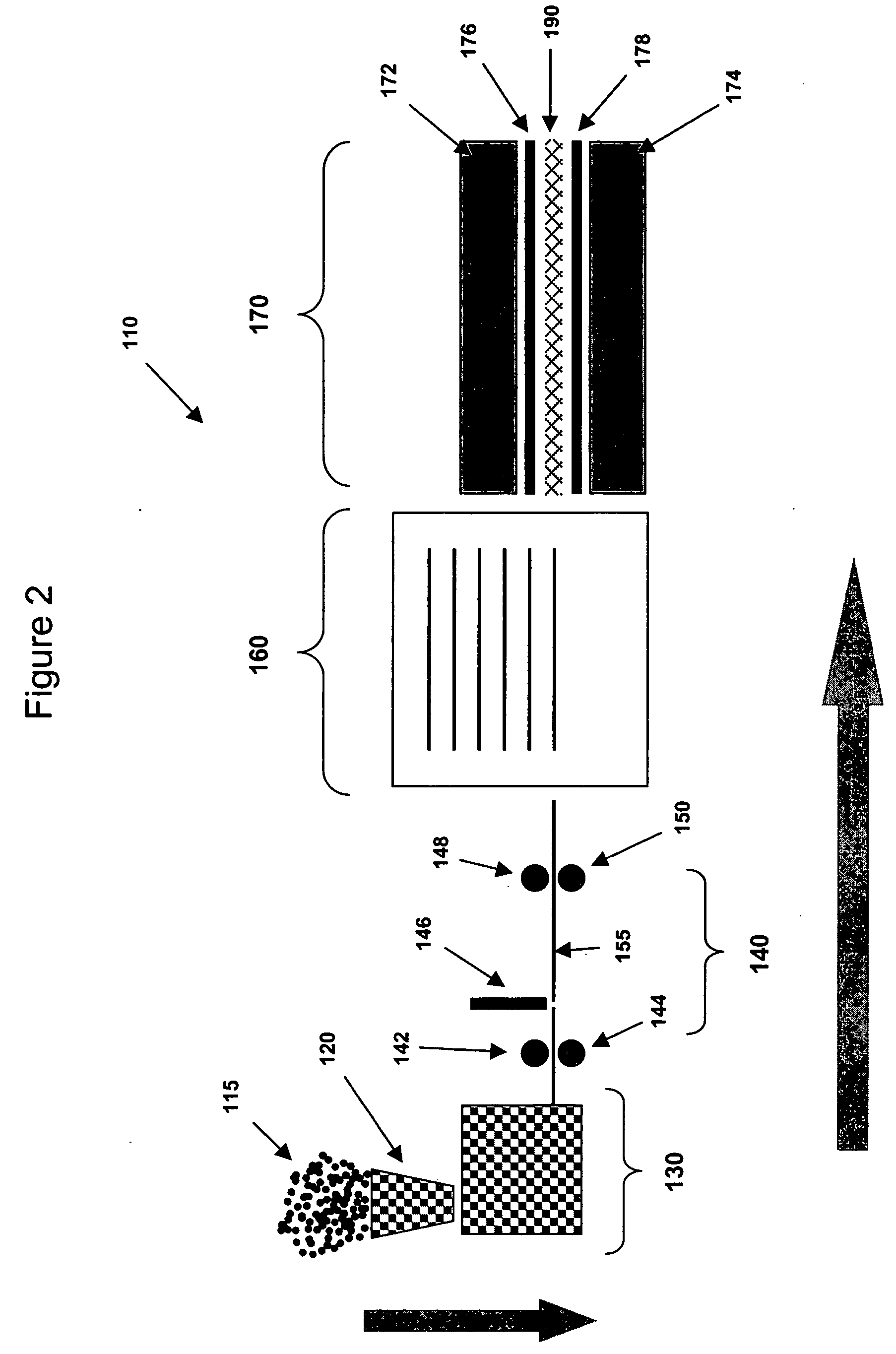
[0047] Referring to FIG. 2, the present invention is shown, generally referred to by reference numeral 110. System 110 has hopper 120, extruder 130, conveyor system 140, and coreformer or expander 170, which are identical to the similarly numbered components of system 10 discussed above. System 110 also has buffer loader 160.

[0048] In system 110, the process for creating the thermoformable materials is the same as that of system 10, up until the point at which sheet 155 is loaded into buffer loader 160. Thus, raw materials 115 are fed into hopper 120, which guides material 115 into extruder 130. Extruder 130 forms sheet 155 out of raw materials 115. Sheet 155 is guided through first upper and lower rollers 142 and 144, and then to shear 146, which cuts sheet 155 to a desired length. Sheet 155 is then guided by second upper and lower rollers 148 and 150 to buffer loader 160.

[0049] Buffer loader 160 holds sheet 155 at an elevated temperature while it is waiting to be loaded into core...

third embodiment

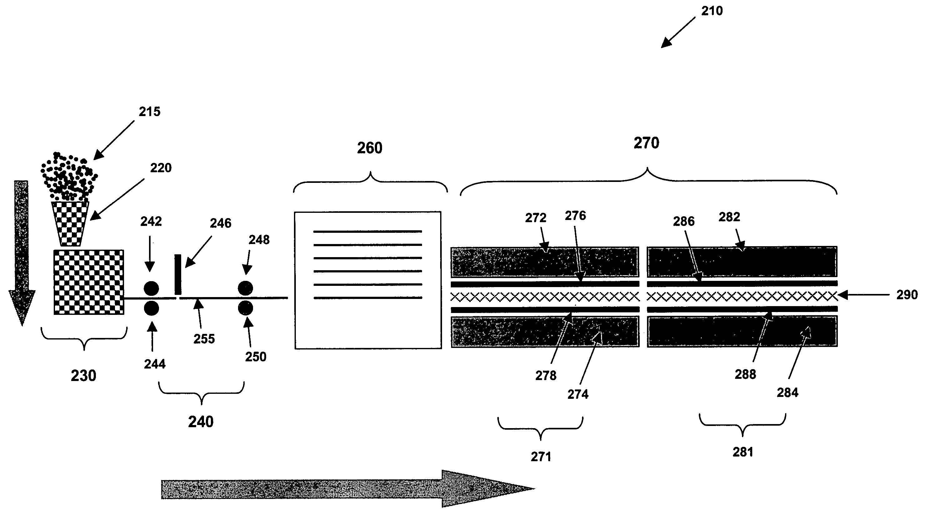
[0052] Referring to FIG. 3, the present invention is shown, generally referred to by reference numeral 210. System 210 has hopper 220, extruder 230, conveyor system 240, and buffer loader 260, which are identical to the similarly numbered components of system 110 discussed above. System 210 also has coreformer or expander 270. Coreformer or expander 270 further has heating station 271 and cooling station 281.

[0053] System 210 performs in a substantially similar manner to system 110, with the important exception that there are two separate stages in coreformer or expander 270, as opposed to the coreformers of the above embodiments. Thus, when sheet 255 leaves buffer loader 260, it enters heating station 271 of coreformer or expander 270 first. Heating station 271 has upper heating press 272 and lower heating press 274. Upper and lower heating platen 276 and 278 are operably connected to upper heating press 272 and lower heating press 274 respectively. Upper and lower heating platens ...


PUM

PropertyMeasurementUnit
Temperatureaaaaaaaaaa
Lengthaaaaaaaaaa
Thicknessaaaaaaaaaa

Abstract

A method and apparatus for continuously and cost-effectively producing expanded thermoformable materials encompassing the steps of: providing raw thermoformable material into an extruder or mold; heating the material in the extruder or mold; extruding or co-extruding molding planar sheet material of suitable engineering performance parameters to a gauge and width; cutting or shearing the extruded or molded material while it is still hot to suitable lengths for expansion in a coreformer; conveying the hot thermoformable sheet material in between forming platens; heating the thermoformable material to a temperature at which the material adhesively bonds to the platens; expanding the cross-section of the thermoformable material; and then cooling the expanded thermoformable material by changing the temperature of the forming platens such that the thermoformable material can maintain its structural integrity and be released from the platens.

Description

CROSS-REFERENCED APPLICATIONS [0001] This application claims priority to U.S. Provisional Patent Application No. 60 / 632,398, filed on Dec. 2, 2004, U.S. Provisional Patent Application No. 60 / 632,420, filed on Dec. 2, 2004, U.S. Provisional Patent Application No. 60 / 632,397, filed on Dec. 2, 2004, and U.S. Provisional Patent Application No. 60 / 676,407, filed on Apr. 29, 2005, all of which are hereby incorporated by reference in their entirety.BACKGROUND OF THE INVENTION [0002] 1. Field of the Invention [0003] The present invention relates to a method of producing expanded thermoformable materials. More particularly, the present invention relates to a cost effective and energy efficient method for continuously producing expanded thermoformable materials with open or closed cell wall structures. [0004] 2. Description of the Prior Art [0005] Processes used to make expanded thermoformable materials typically involve placing a thermoformable polymeric material blank between mold plates, w...

Claims


Application Information

Patent Timeline
IPC IPC(8): B29C47/00B29C48/08B29C48/11
CPCB29C44/0461B29C44/08B29C44/3415B29C44/3484B29C47/0019B29C47/065B29C47/14B29C47/145B29C51/00B29C2793/009B29K2105/04B29K2105/06B29K2105/16B29K2105/162B29K2105/256B29K2105/26B29K2995/0003B29K2995/001B82Y30/00B29C48/07B29C48/21B29C48/305B29C48/307B29C48/11B29C48/08
Inventor ST. DENIS, THOMASKARAMANIS, GABRIEL M.AUSTIN, MARK
Owner PANTERRA ENGINEERED PLASTICS
Why Eureka
Try Eureka