
Luminescent light source and luminescent light source array

a luminescent light source and light source array technology, applied in lighting and heating apparatus, bridges, instruments, etc., can solve the problems of difficult manufacturing of reflecting mirrors, increased cost, irregular color of luminescent light sources, etc., to improve the degree of freedom in optical design, improve the number of divisions of reflecting mirrors, and finely adjust the light output direction

Active Publication Date: 2006-07-20
ORMON CORP
View PDF6 Cites 88 Cited by
  • Summary
  • Abstract
  • Description
  • Claims
  • Application Information

AI Technical Summary

Benefits of technology

The present invention provides a luminescent light source that can increase the number of divisions of a reflecting mirror without narrowing the pitch interval of the reflection areas. This allows for more detailed adjustment of the light output direction and equalization of optical intensity distribution. The light source also has improved color uniformity and reduced color irregularity. The arrangement of reflection areas in a mosaic pattern allows for more detailed adjustment of the light path and more detailed adjustment of the light output direction. The reflection areas can have different shapes, and the light use efficiency can be increased by arranging them with little or no space between them. The degree of freedom in designing the light path is increased, and more detailed adjustment of the light output direction and optical intensity or color uniformity can be achieved.

Problems solved by technology

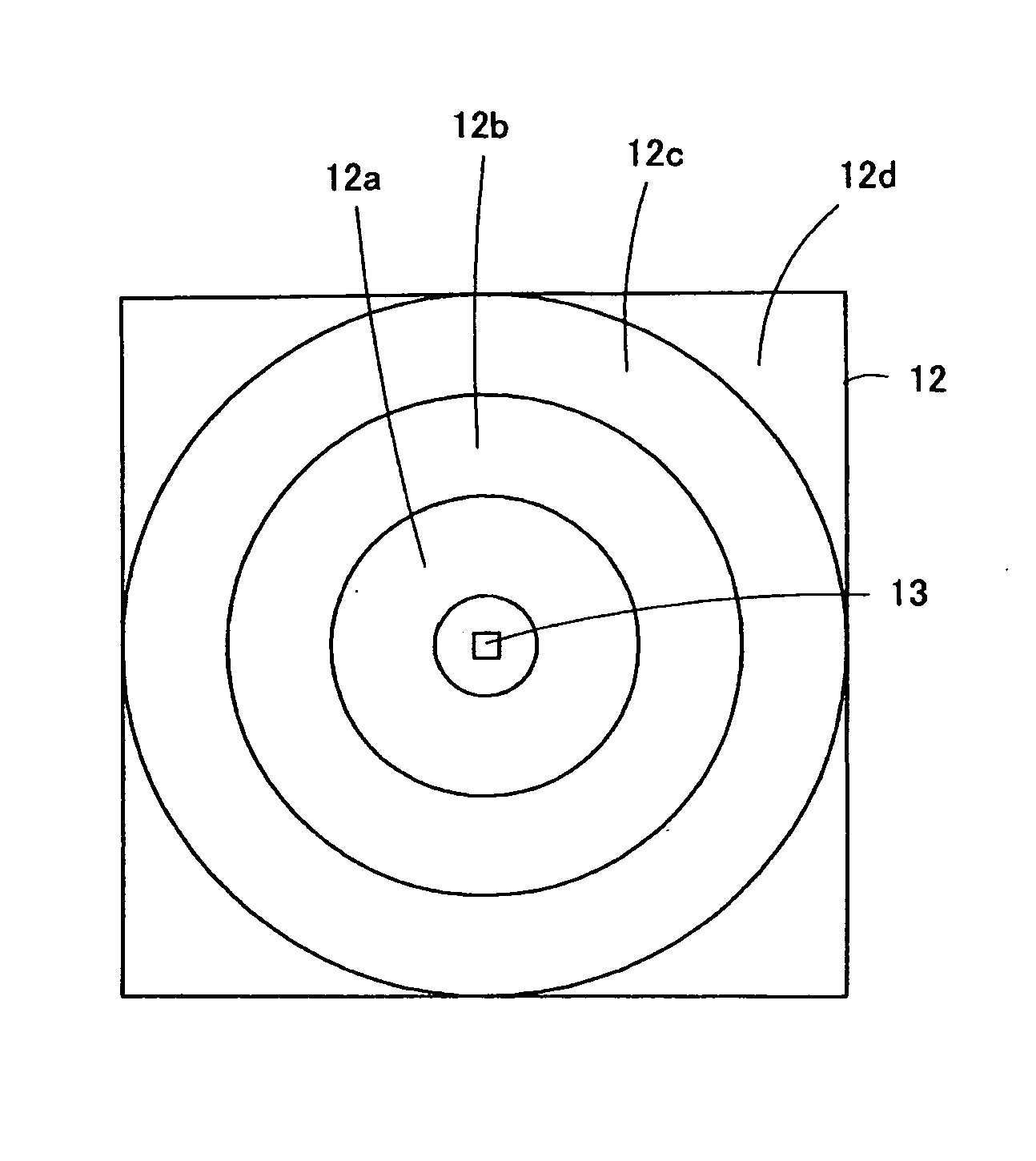
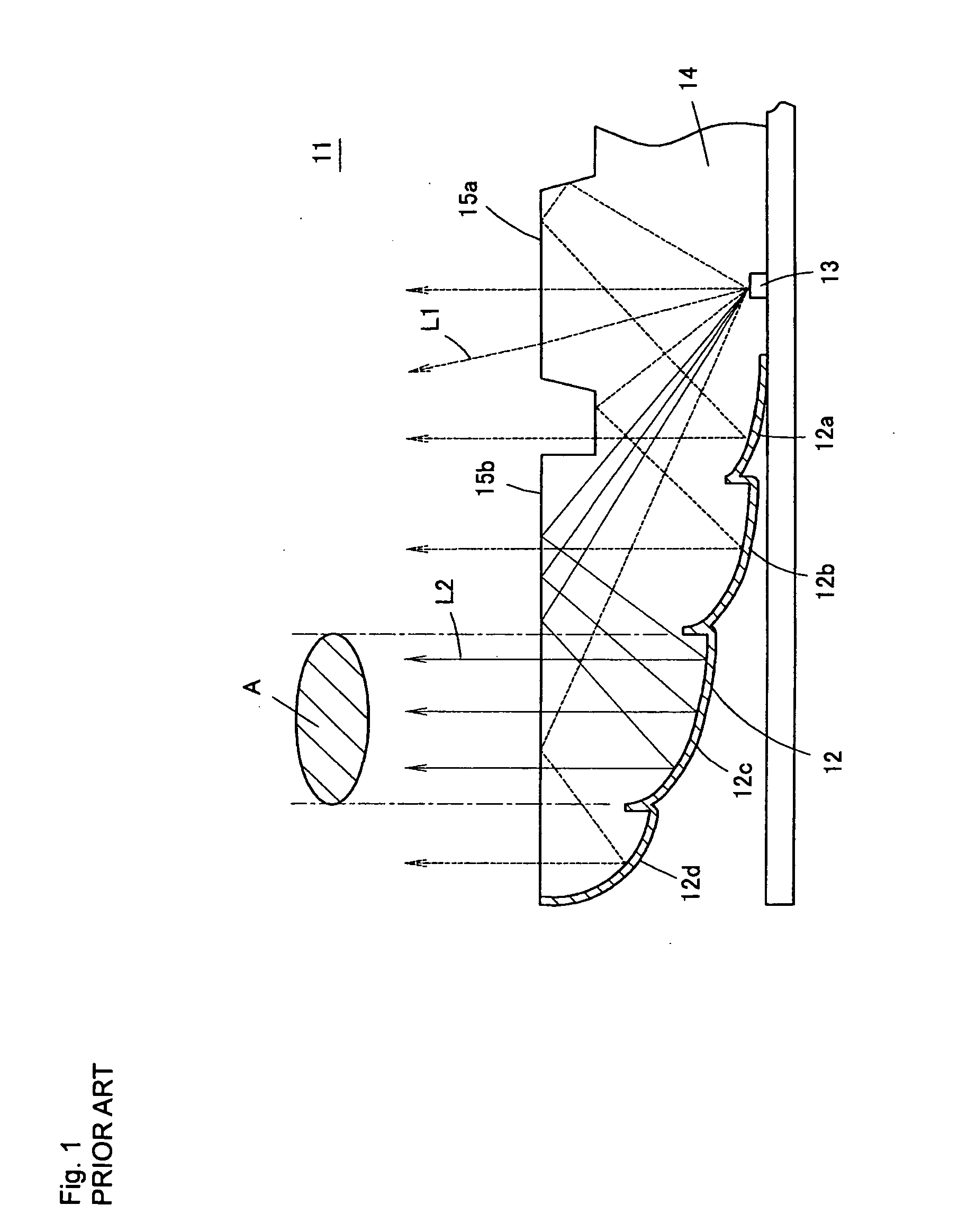
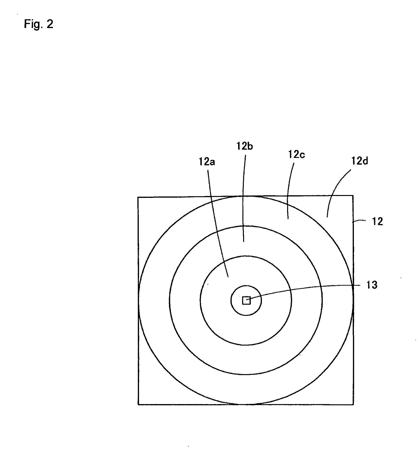
However, in the luminescent light source 11 configured as described above, when three light emitting devices of red, green and blue, for instance, are arranged in the central area of the reflecting mirror 12 to configure a white light source, each color will be separated, leading to the problem of irregular color in the luminescent light source 11.
Thus, although use of the reflecting mirror 12 as shown in FIG. 6 could improve color uniformity of a luminescent light source, increased number of divisions will narrow the pitch interval of a reflection area, thus making it difficult to manufacture a reflecting mirror, and increasing cost.
In other words, there is the problem that as the number of the divisions of the reflecting mirror 12 increases, a balance between performance improvement and the cost will be lost.
Such the arrangement cannot be implemented with the ring zone shaped reflection areas.

Method used


Image

  • Luminescent light source and luminescent light source array
  • Luminescent light source and luminescent light source array
  • Luminescent light source and luminescent light source array

Examples


embodiment 1

[0123]FIG. 7 shows a partly broken perspective view of a luminescent light source 21 according to Embodiment 1 of the present invention. FIG. 8 shows a perspective view of the luminescent light source that is viewed from the rear side and from which a wiring board has been removed. FIG. 9A and B show perspective views, viewed from the front side and from the rear side, respectively, of a mold unit 22 (light guide unit) on the rear side of which a reflecting mirror 26 is formed. In addition, FIGS. 10A, B and C show a front elevation, a back side view, and a bottom plan view of the mold unit 22. FIG. 11A shows a front elevation of the luminescent light source 21, FIG. 11(b) shows a cross sectional view in X-X direction (diagonal direction) of FIG. 11A, and FIG. 11(c) shows a cross sectional view in Y-Y direction (opposite side direction) of FIG. 11A.

[0124] In the luminescent light source 21, an substantially dish-shaped mold unit (light guide unit) 22 is formed of optically-transpare...

embodiment 2

[0212]FIG. 78 shows a front elevation of the luminescent light source array 50 according to Embodiment 2 of the present invention. The luminescent light source array 50 is an array of the luminescent light sources 21 according to the invention either without a gap or with some gap in the same plane. The luminescent light source array 50 is used as a liquid crystal display or a backlight for liquid crystal display television, or a lighting system, and is advantageous in that it is thin, has excellent color reproducibility, is less susceptible to color irregularity, and has high color uniformity.

[0213] In addition, if the luminescent light source array 50 using the luminescent light source 21 of the present invention is used as a backlight, the front space (space to the target surface) needed for equalization of optical intensity and color mixing degree can be short, information display equipment (e.g., a liquid crystal display to be discussed later) in which the luminescent light so...

embodiment 3

[0215]FIG. 79 shows a schematic cross section of the structure of a liquid crystal display (liquid crystal display device) 51 according to Embodiment 3 of the present invention. The liquid crystal display 51 is comprised by arranging a backlight 53 on the rear of a liquid crystal panel 52. The liquid crystal panel is a general one, and comprised by sequentially laminating a polarization plate 54, a liquid crystal cell 55, a phase difference plate 56, a polarization plate 57 and antireflection film 58 from the rear.

[0216] The backlight 53 is comprised by placing a light diffusion film 61, a prism sheet 62 and a luminance improvement film 63 on the front face on the luminescent light source array 50 on which a plurality of luminescent light sources 21 are arranged. As described later, the luminescent light source 21 is formed like a square when viewed from the front, and the luminescent light source array 50 is comprised by arrangement of about one hundred or several hundreds of the ...


PUM


Abstract

To provide a luminescent light source that can increase the number of divisions of a reflecting mirror without reducing pitch interval of reflection areas. A luminescent light source comprises a reflecting mirror for reflecting light, a mold unit arranged on a light reflection surface of the reflecting mirror, and light emitting devices of three luminescent devices of red, blue and green that are placed in the central part and output light to the mold unit. In the reflecting mirror, rectangular reflection areas are arranged vertically and horizontally in a grid.

Description

BACKGROUND OF THE INVENTION [0001] 1. Field of the Invention [0002] This invention relates to a luminescent light source and a luminescent light source array, and, more specifically, to a luminescent light source or a luminescent light source array using an LED (light emitting diode) chip. In addition, the invention relates to a lighting system or a liquid crystal display device, etc. [0003] 2. Description of the Related Art [0004] A luminescent light source that has a large area and high light use efficiency is disclosed in Patent Document 1. FIG. 1 shows a cross sectional view of a part of such a luminescent light source. In the luminescent light source 11, a white-color or monochromatic light emitting device 13 is arranged in the central part of the back side of a mold unit 14 made of transparent resin, and a reflecting mirror 12 is formed by depositing a metal thin film such as Al or Au, Ag, etc. in a concentric pattern formed on the back side of the mold unit 14. FIG. 2 shows a...

Claims


Application Information

Patent Timeline
Patent Type & Authority Applications(United States)
IPC IPC(8): F21V7/04F21V7/00H01L33/54H01L33/56H01L33/60
CPCF21K9/00F21V7/0091F21V7/04F21V7/09F21Y2101/02G02B5/09G02B17/086G02B19/0066G02B19/0028G02B19/0061F21Y2115/10F21K9/68E01D19/02E01D2101/285
Inventor AYABE, TAKAHIROMATSUI, AKIRAKIYOMOTO, HIRONOBU
Owner ORMON CORP
Learn More