Vascular graft and deployment system

a technology of vascular grafts and deployment systems, which is applied in the field of vascular grafts and vascular graft deployment systems, can solve the problems of high mortality, large risk, and rupture of the sac, and achieve the effect of reducing the risk of vascular grafts and vascular grafts

Inactive Publication Date: 2006-07-20
JACQUES SEGUIN
View PDF89 Cites 98 Cited by
  • Summary
  • Abstract
  • Description
  • Claims
  • Application Information

AI Technical Summary

Problems solved by technology

When left untreated, the aneurysm may eventually cause rupture of the sac with ensuing fatal hemorrhaging in a very short time.
High mortality associated with the rupture led initially to transabdominal surgical repair of abdominal aortic aneurysms.
Surgery involving the abdominal wall, however, is a major undertaking with associated high risks.
There is considerable mortality and morbidity associated with this magnitude of surgical intervention, which in essence involves replacing the diseased and aneurysmal segment of blood vessel with a prosthetic device which typically is a synthetic tube, or graft, usually fabricated of Polyester, Urethane, DACRON™, TEFLON.™, or other suitable material.
Thus, if the patient is not receiving routine examinations, it is possible that the aneurysm will progress to the rupture stage, wherein the mortality rates are significantly higher.
Disadvantages associated with the conventional, prior art surgery, in addition to the high mortality rate include the extended recovery period associated with such surgery; difficulties in suturing the graft, or tube, to the aorta; the loss of the existing aorta wall and thrombosis to support and reinforce the graft; the unsuitability of the surgery for many patients having abdominal aortic aneurysms; and the problems associated with performing the surgery on an emergency basis after the aneurysm has ruptured.
Since the graft must be secured, or sutured, to the remaining portion of the aorta, it is many times difficult to perform the suturing step because the thrombosis present on the remaining portion of the aorta, and that remaining portion of the aorta wall may many times be friable, or easily crumbled.
Since many patients having abdominal aortic aneurysms have other chronic illnesses, such as heart, lung, liver, and / or kidney disease, coupled with the fact that many of these patients are older, the average age being approximately 67 years old, these patients are not ideal candidates for such major surgery.
This complicates the surgical procedure and makes it more time consuming.
In addition, the connection between the two parts may leak and cause blood to enter the aneurysm.

Method used


Image

  • Vascular graft and deployment system
  • Vascular graft and deployment system
  • Vascular graft and deployment system

Examples


Embodiment Construction

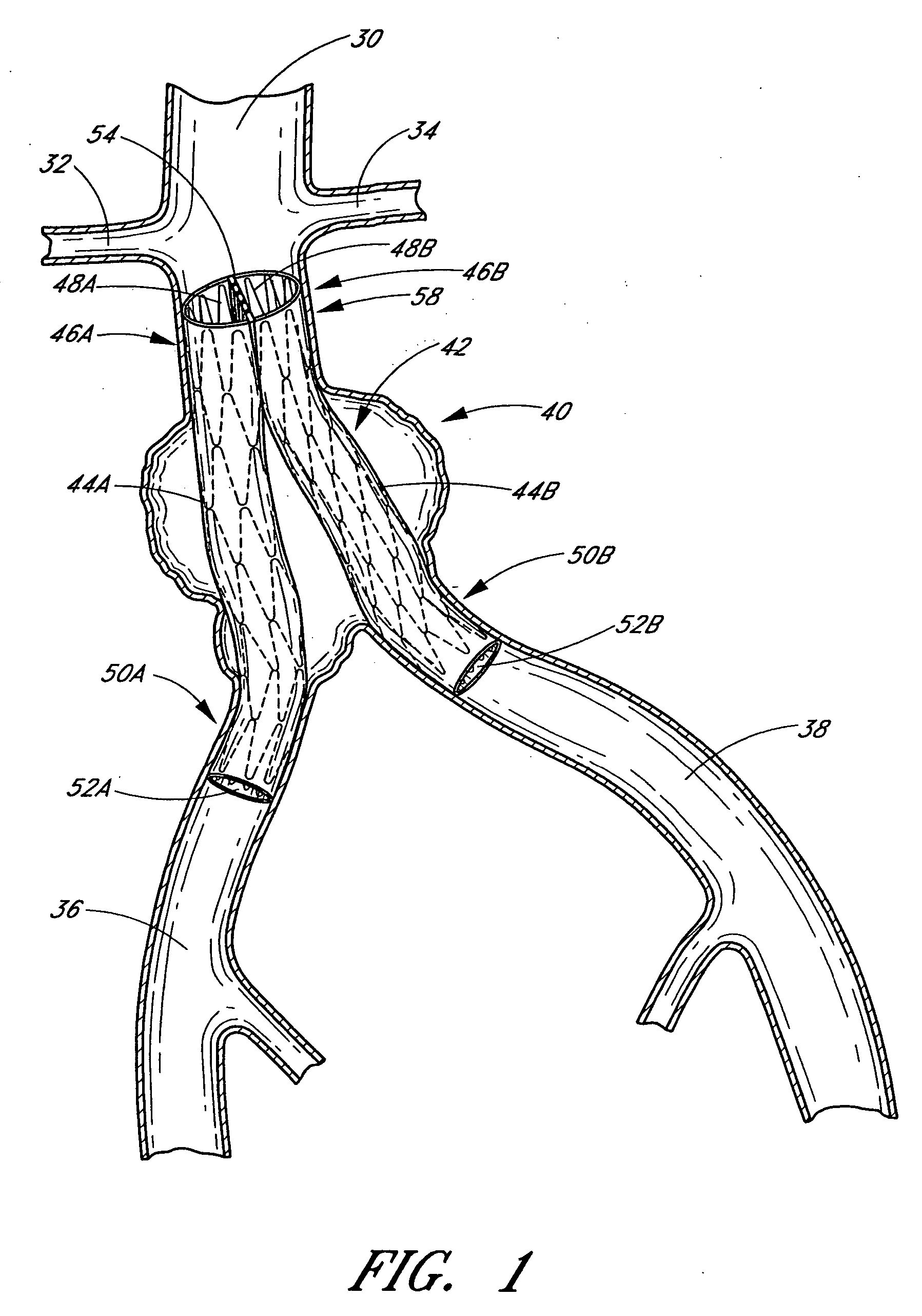
[0047]FIG. 1 illustrates a schematic representation of the abdominal part of the aorta and its principal branches. In particular, the abdominal aorta 30 is characterized by a right renal artery 32 and left renal artery 34. The large terminal branches of the aorta 30 are the right and left common iliac arteries 36 and 38. Additional vessels (e.g., second lumbar, testicular, inferior mesenteric, middle sacral) have been omitted for simplification. An aneurysm 40 is illustrated in the infrarenal portion of the diseased aorta. An endoluminal vascular prosthesis 42, in accordance with an embodiment of the present invention, is illustrated spanning the aneurysm 40.

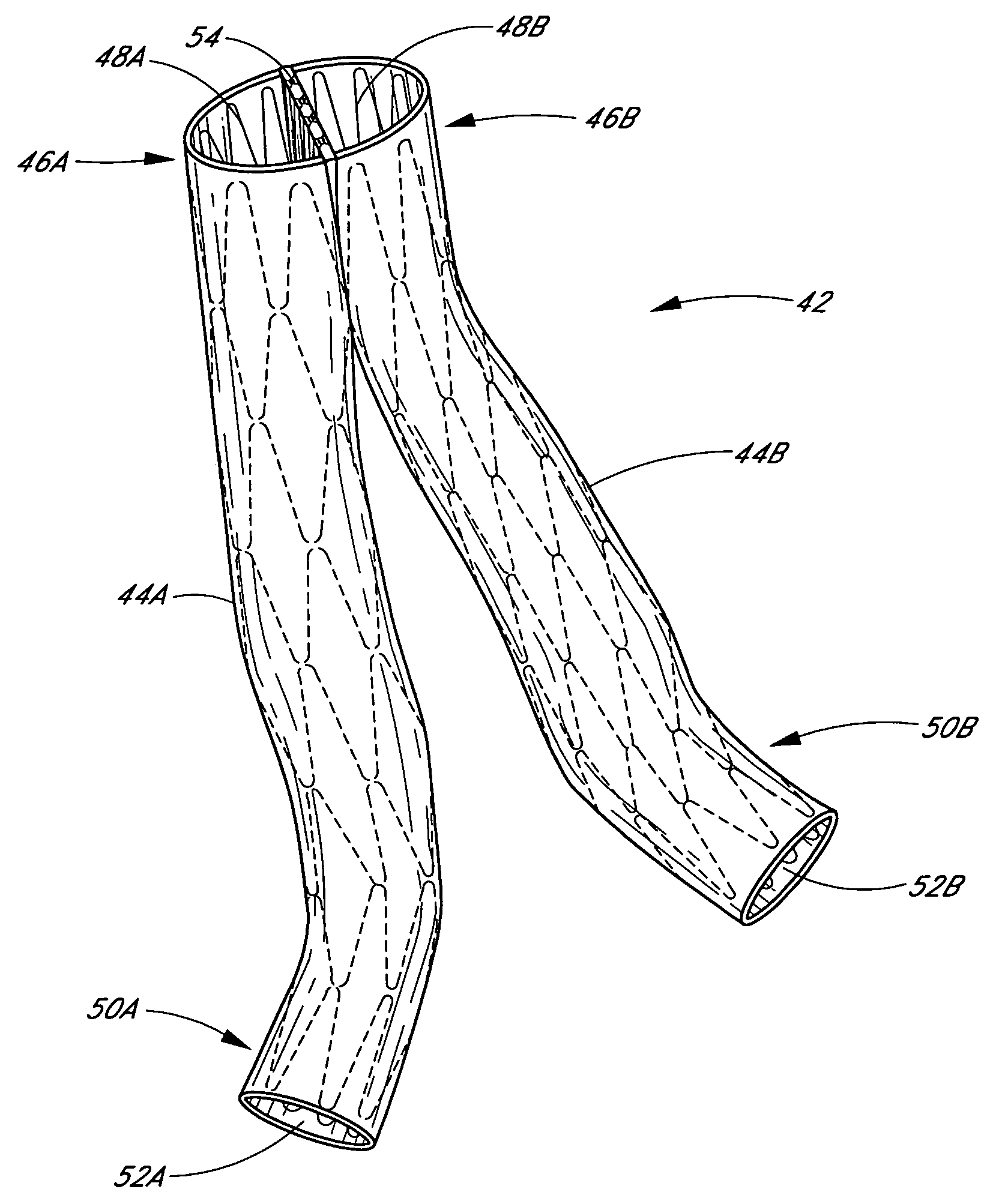
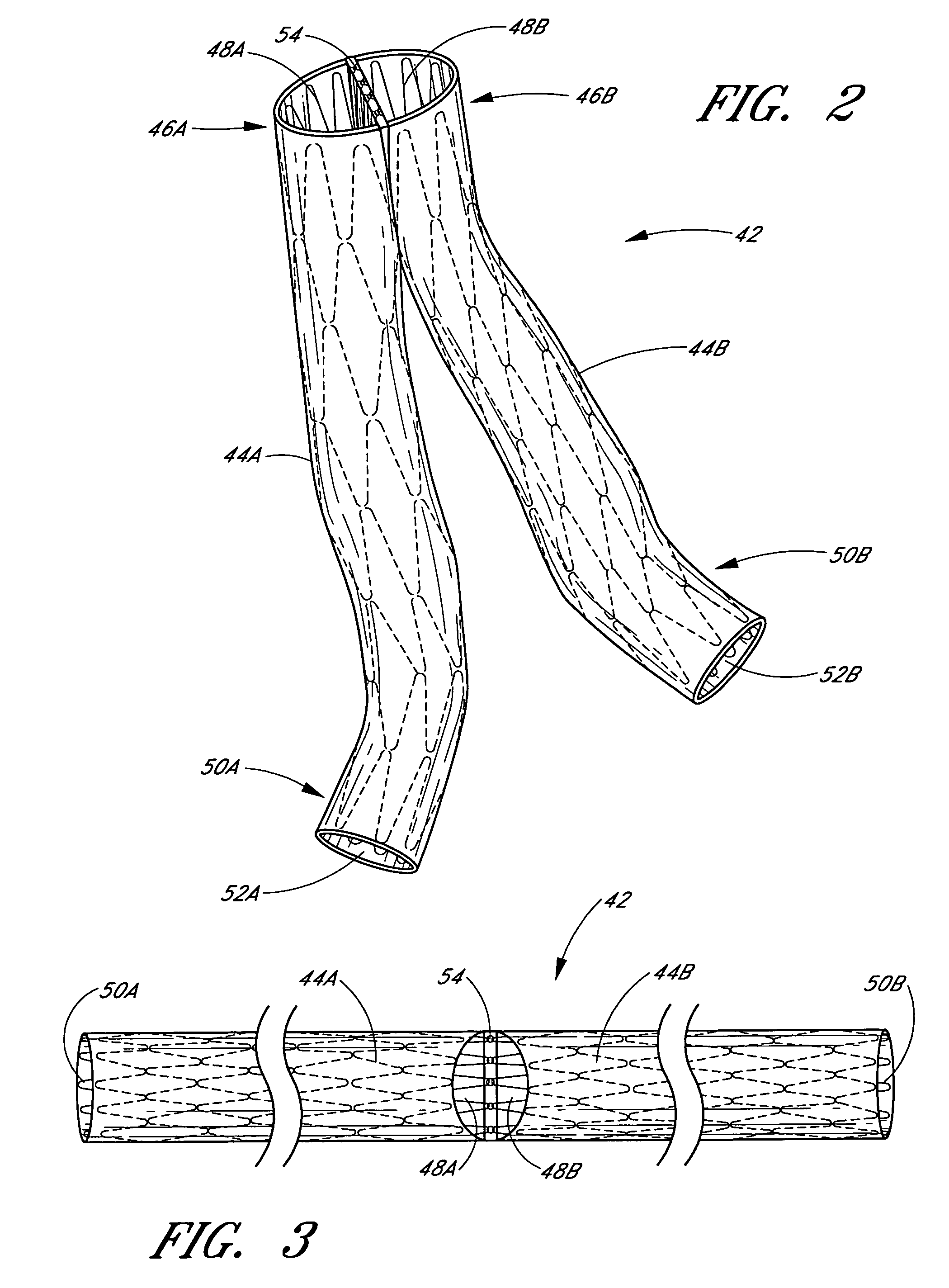
[0048] With reference to FIGS. 1-4, the prosthesis 42 comprises a first tubular member or tube 44A and a second tubular member or tube 44B. The first tubular member 44A has a device distal end 46A, which defines a device distal opening 48A, and a device proximal end 50A, which defines a proximal opening 52A. In a similar manner...


PUM


Abstract

Disclosed is a method and apparatus for treating bifurcations of the vascular system, such as abdominal aneurysms at the bifurcation of the aorta and iliac arteries. A tubular implant having a first section, a second section and a magnetic connection therebetween is positioned across the bifurcation such that the proximal ends of the first and second sections extends into a first iliac and a second iliac respectively. Deployment catheters are also disclosed.

Description

PRIORITY INFORMATION [0001] This application claims the benefit under 35 USC §119(e) of U.S. Provisional Application No. 60 / 624,692, filed Nov. 3, 2005 and is a continuation-in-part of application Ser. No. 10 / 836,317, filed Apr. 30, 2004, claims the benefit under 35 USC §119(e) of U.S. Provisional Application No. 60 / 467,625, filed May 2, 2003.BACKGROUND OF THE INVENTION [0002] 1. Field of the Invention [0003] The present invention relates to vascular grafts and vascular graft deployment systems. [0004] 2. Description of the Related Art [0005] An abdominal aortic aneurysm is a sac caused by an abnormal dilation of the wall of the aorta, a major artery of the body, as it passes through the abdomen. The abdomen is that portion of the body which lies between the thorax and the pelvis. It contains a cavity, known as the abdominal cavity, separated by the diaphragm from the thoracic cavity and lined with a serous membrane, the peritoneum. The aorta is the main artery, or artery, from whic...

Claims


Application Information

Patent Timeline
Patent Type & Authority Applications(United States)
IPC IPC(8): A61F2/06
CPCA61F2/07A61F2/856A61F2002/067A61F2002/075A61F2002/8486A61F2230/0034A61F2250/0045A61F2/89A61F2/90A61F2002/072A61F2230/0054
Inventor SEGUIN, JACQUES
Owner JACQUES SEGUIN
Why Eureka
Try Eureka