Blower, cooling device including the blower, and electronic apparatus including the cooling device

Inactive Publication Date: 2006-07-27
PANASONIC CORP
View PDF7 Cites 44 Cited by
  • Summary
  • Abstract
  • Description
  • Claims
  • Application Information

AI Technical Summary

Benefits of technology

[0017] According to a third aspect of the invention, a highly thermal conductive metallic member is used for a thermal connection part between the liquid refrigerant within the reserve tank and the member forming an air-blowing path of the fan. Thus, the conductivity of heat from the liquid refrigerant within the reserve tank to the fan casing to form an air-blowing path of the fan, the radiator, or the separately provided duct is further improved. This can promote heat exchange to improve the heat radiation property.
[0018] According to a fourth aspect of the invention, the reserve tank constitutes a portion of the member forming an air-blowing path of the fan. Thus, the thermal connectivity between the liquid refrigerant within the reserve tank and the fan casing to form an air-blowing path of the fan, the radiator, or the separately provided duct becomes easier. This can not only improve the cooling performance of the cooling device but also reduce the number of components. Therefore, the whole cooling device can be more easily made small as well as manufacture of the cooling device becomes easy.
[0019] According to a fifth aspect of the invention, a partition plate to form a bypass channel for the liquid refrigerant is provided within the reserve tank. Thus, stagnation of the liquid refrigerant within the reserve tank can be prevented, thereby promoting heat exchange and reducing heat storage effects. This can improve the heat radiation property of the cooling device as much.
[0020] According to a sixth aspect of the invention, heat-receiving fins are provided within the reserve tan

Problems solved by technology

Accordingly, when the radiator, the fan, the reserve tank, etc. that constitute a heat-radiating part are installed near the heating element or in a place where ambient temperatu

Method used


Image

  • Blower, cooling device including the blower, and electronic apparatus including the cooling device
  • Blower, cooling device including the blower, and electronic apparatus including the cooling device
  • Blower, cooling device including the blower, and electronic apparatus including the cooling device

Examples


first embodiment

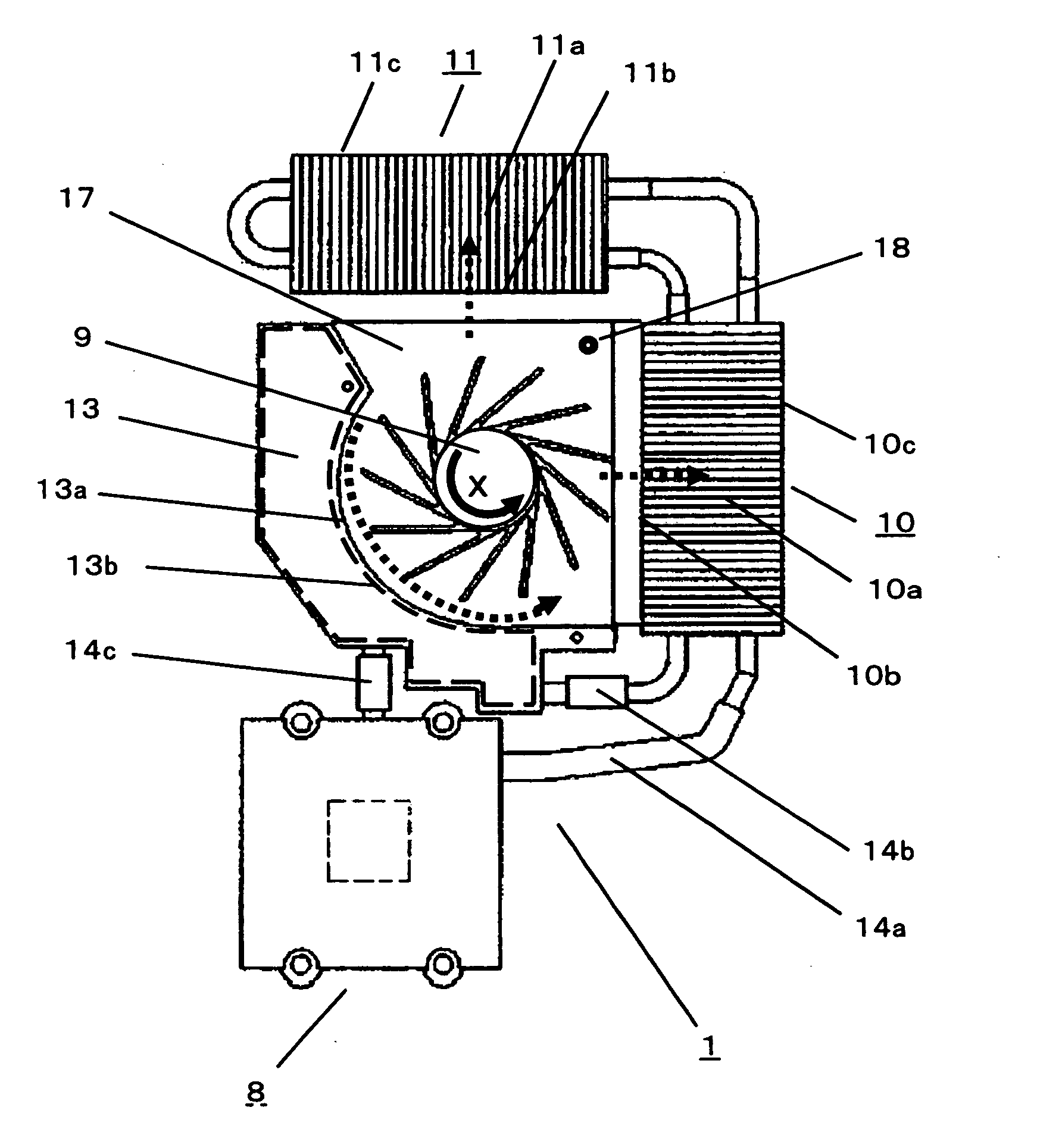
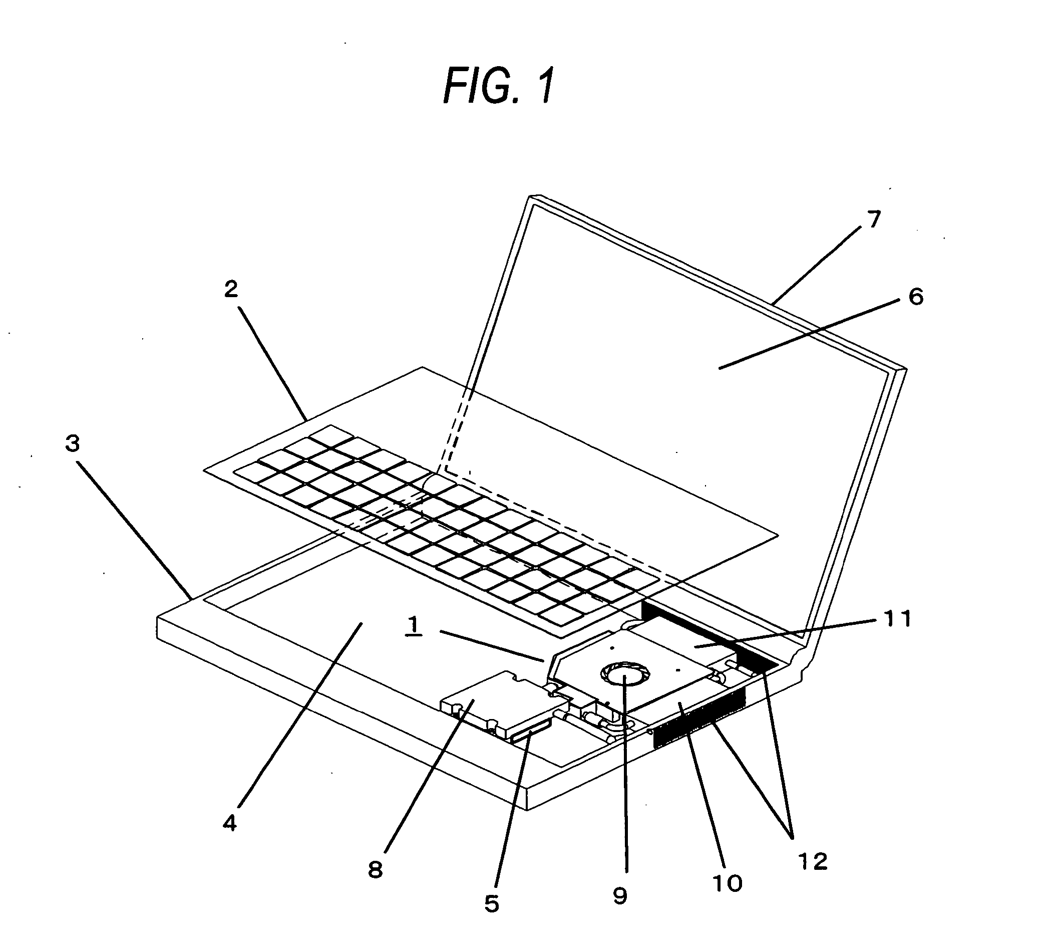
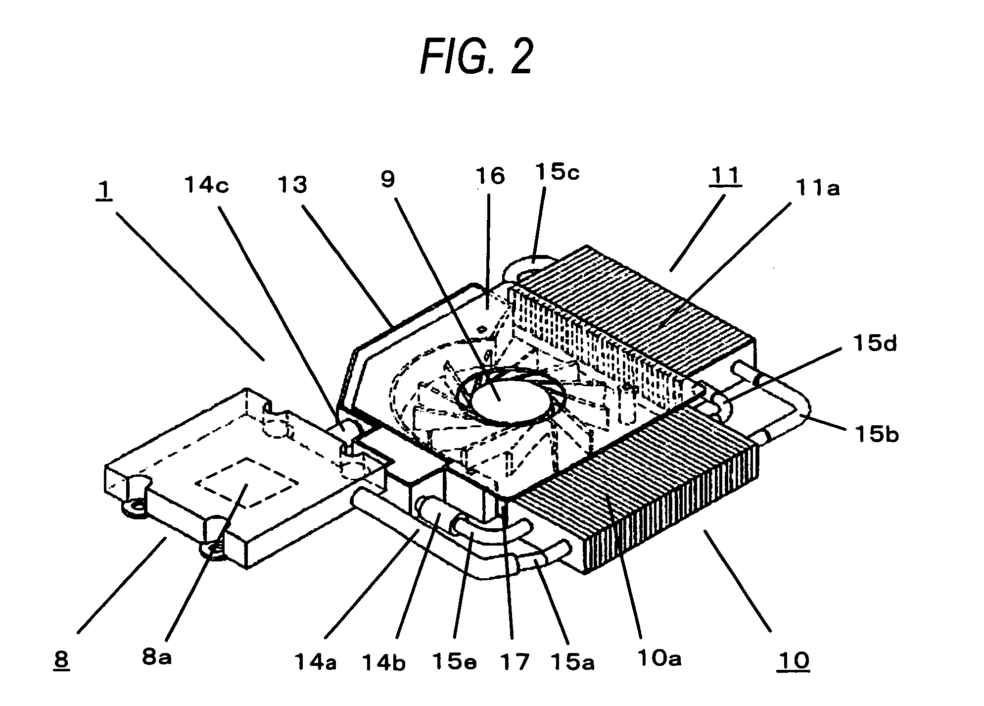
[0033] In FIGS. 1 to 4, FIG. 1 illustrates the entire structure of an electronic apparatus incorporating a cooling device according to A first embodiment of the invention, FIG. 2 is a perspective view of the cooling device according to The first embodiment of the invention, FIG. 3 is a perspective view of the cooling device according to the first embodiment of the invention, with its fan cover removed, and FIG. 4 is a plan view of the cooling device according to the first embodiment of the invention, with its fan cover removed.

[0034] First, FIG. 1 illustrates the entire structure of an electronic apparatus incorporating a cooling device 1. In this figure, the electronic apparatus is shown, with a keyboard 2 slightly floated from its regular position in order to more easily understand the inner structure thereof.

[0035] The electronic apparatus includes a first housing 3 of the electronic apparatus having a keyboard 2 mounted on its top face, a heating element 5 having a particularl...

second embodiment

[0053]FIG. 5 is a plan view of a cooling device according to a second embodiment of the invention. Referring to this figure, a plurality of heat-receiving fins 13c are formed on an inner wall 13b of a reserve tank 13 on the side where an air-blowing path is to be formed. Here, it is preferable that the heat-receiving fins 13c be fabricated of highly thermal conductive metal member, for example, metallic material, such as aluminum and copper. Also, since the heat-receiving fins 13c can further increase the area to be in contact with the liquid refrigerant within the reserve tank 13, the conductivity of heat from the liquid refrigerant to the outer wall 13a of the reserve tank 13 forming an air-blowing path of the fan 9 can be improved. Therefore, the heat radiation property of the cooling device can be further enhanced.

[0054] Moreover, a thermal connection is also established between the reserve tank 13 and the radiator 10 forming an air-blowing path of the fan 9 by a connecting mem...

third embodiment

[0058]FIG. 7 illustrates the entire structure of an electronic apparatus incorporating a cooling device according to a third embodiment of the invention. This figure shows a first housing 3 of the electronic apparatus having a keyboard 2 mounted on its top face, a heating element 5 having a particularly large calorific value, such as a CPU mounted on an electronic circuit board 4 that is received in the first housing 3 and on which electronic components, etc. are arranged, a second housing 7 of the electronic apparatus having a display device 6 that displays processing results by the CPU, a heat receiver 20 that comes into close contact with the heating element 5 to receive heat from the heating element 5 and exchanges heat with the liquid refrigerant to cool the heating element 5, and a pump 21 for circulating the liquid refrigerant through the cooling device. As the heat receiver 20, highly thermal conductive, metallic material, such as metal, including aluminum and copper, and al...


PUM


Abstract

The invention provides a cooling device including a heat-receiver integrated pump that has a heat-receiving part provided on one side thereof and delivers toward a connecting pipe liquid refrigerant on which a heat exchange has been performed through the heat-receiving part. A first radiator having a plurality of radiation fins radiates heat by exchanging heat with the liquid refrigerant sent via the connecting pipe. A second radiator having a plurality of radiation fins radiates heat by exchanging heat with the liquid refrigerant similarly to the first radiator. A fan blows air toward the first radiator and the second radiator. A base, constituting a fan casing, regulates an air-blowing direction of the fan, and includes a fan cover and a reserve tank. Liquid refrigerant within the reserve tank is thermally connected to a member forming an air-blowing path of the fan.

Description

BACKGROUND OF THE INVENTION [0001] 1. Field of the Invention [0002] The present invention relates to a cooling device used for a cooling system using heat pipes or for a liquid cooling system that performs forced circulation of liquid refrigerant by using a pump for the purpose of forced cooling of various heating elements, such as a central processing unit (hereinafter referred to as CPU), chipsets, a display controller, an HDD, etc. that are arranged within a housing of an electronic apparatus, and an electronic apparatus including the cooling device. [0003] 2. Description of the Related Art [0004] The movement toward improvement in the speed of data processing in recently developed computers is very rapid, and the clock frequency of CPUs is becoming markedly fast as compared with before. As a result, the calorific value of the CPUs increases. In addition to a method of bringing heat sinks or heat radiation fins serving as heat-radiating parts into contact with heating elements to...

Claims


Application Information

Patent Timeline
IPC IPC(8): H05K7/20
CPCG06F1/203G06F2200/201G06F2200/203H01L23/473H01L2924/0002H01L2924/00
Inventor AIZONO, YOSHIMITUNARAKINO, SHIGERUHIRAKAWA, FUMINORI
Owner PANASONIC CORP
Why Eureka
Try Eureka