Batch pyrolysis system

a pyrolysis system and batch technology, applied in the field of continuous batch pyrolysis systems, can solve the problems of difficult opening of new sites, less availability of storage or land filling sites of waste tires, and major environmental problems of waste vehicle tires, and achieve the effect of high throughput and high quality

a pyrolysis system and batch technology, applied in the field of continuous batch pyrolysis systems, can solve the problems of difficult opening of new sites, less availability of storage or land filling sites of waste tires, and major environmental problems of waste vehicle tires, and achieve the effect of high throughput and high quality

US20060163053A1Inactive Publication Date: 2006-07-27ERSHAG BENGT STURE

Image

  • Batch pyrolysis system
  • Batch pyrolysis system
  • Batch pyrolysis system

Examples


Embodiment Construction

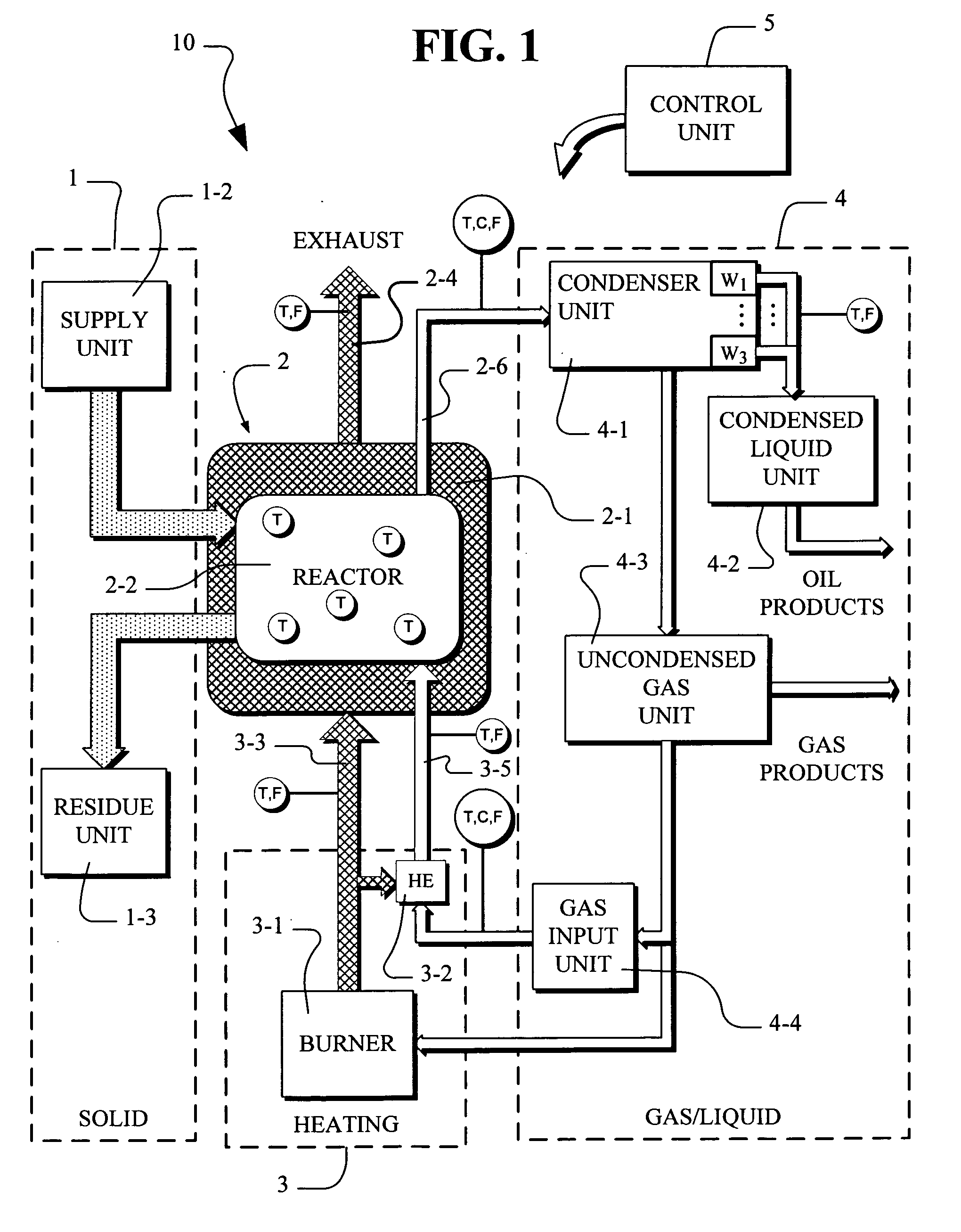
[0041]FIG. 1, a schematic block diagram of the batch pyrolysis system 10 is shown. The batch pyrolysis system 10 includes the solid processing units 1, the reactor 2, the heating units 3, the gas / liquid units 4 and the control unit 5.

[0042] In FIG. 1, the solid processing units 1 include the supply unit 1-2 and the residue unit 1-3. The supply unit 1-2 functions to introduce waste tires or other supply material into the reactor 2. The waste tires can be either in the form of whole tires or cut tires. Typically, tires are washed and cleaned in a washing machine in supply unit 1-2 to remove foreign matter such as dirt, oil, sand or other undesirable material. The cleaning is done with heated water or steam generated by fuel or heat available from the pyrolysis system 10. The cleaning process also typical functions to preheat the waste tires prior to placement in the reactor 2-2. The waste tires are placed into the reactor 2 in either a whole or cut condition. When cut, the cutting ca...


PUM

PropertyMeasurementUnit
temperaturesaaaaaaaaaa

Abstract

Disclosed is a scaleable pyrolysis system for batch processing of waste vehicle tires and other waste to provide pyrolysis products. The core pyrolysis system includes one or more batch reactors, heating units, solids processing units, gas / liquid processing units and control units. In operation, the temperature gradients internal to the reactor are controlled by preferential channeling of heat to provide pyrolysis products that are of high quality, and hence commercially advantageous, while facilitating high throughput.

Description

BACKGROUND OF THE INVENTION [0001] The present invention relates to continuous batch pyrolysis systems for continuous recovery of carbon, hydrocarbons and other materials from waste vehicle tires. [0002] Waste vehicle tires are a major environmental problem. Waste tires in the past have often been discarded in disposal and landfill sites. Sites for storage or land fill of waste tires, however, are becoming less available. Many existing sites for waste tires are reaching capacity with an estimated 3 billion waste tires discarded in sites in the United States. New sites are difficult to open because of increasingly stringent government regulations and public concerns about the environment. Most states now have laws prohibiting the dumping of waste tires in disposal sites. [0003] Tire sites are not only unsightly but they present a risk of being set on fire. When tire sites are set on fire, the burning of tires is environmentally harmful since tire combustion produces dangerous substan...

Claims


Application Information

Patent Timeline
27 Jul 2006
Publication
US20060163053A1
IPC
C10B51/00; C10B57/04; C10B27/00
CPC
C10B47/16; C10B51/00; C10B53/07; Y02P20/143
Inventors
ERSHAG, BENGT-STURE