

Semiconductor chip electrical connection structure
a technology of semiconductor chip and electrical connection, applied in the direction of semiconductor device details, semiconductor/solid-state device details, electrical apparatus, etc., can solve the problems of inability to print stencils, difficulty in reducing size, and difficulty in putting solder material on contact pads of circuit boards through such small stencil openings, so as to simplify fabrication processes and interface integration, and effectively provide outward electrical extension
- Summary
- Abstract
- Description
- Claims
- Application Information
AI Technical Summary
Benefits of technology
Problems solved by technology
Method used
Image

Examples
Embodiment Construction
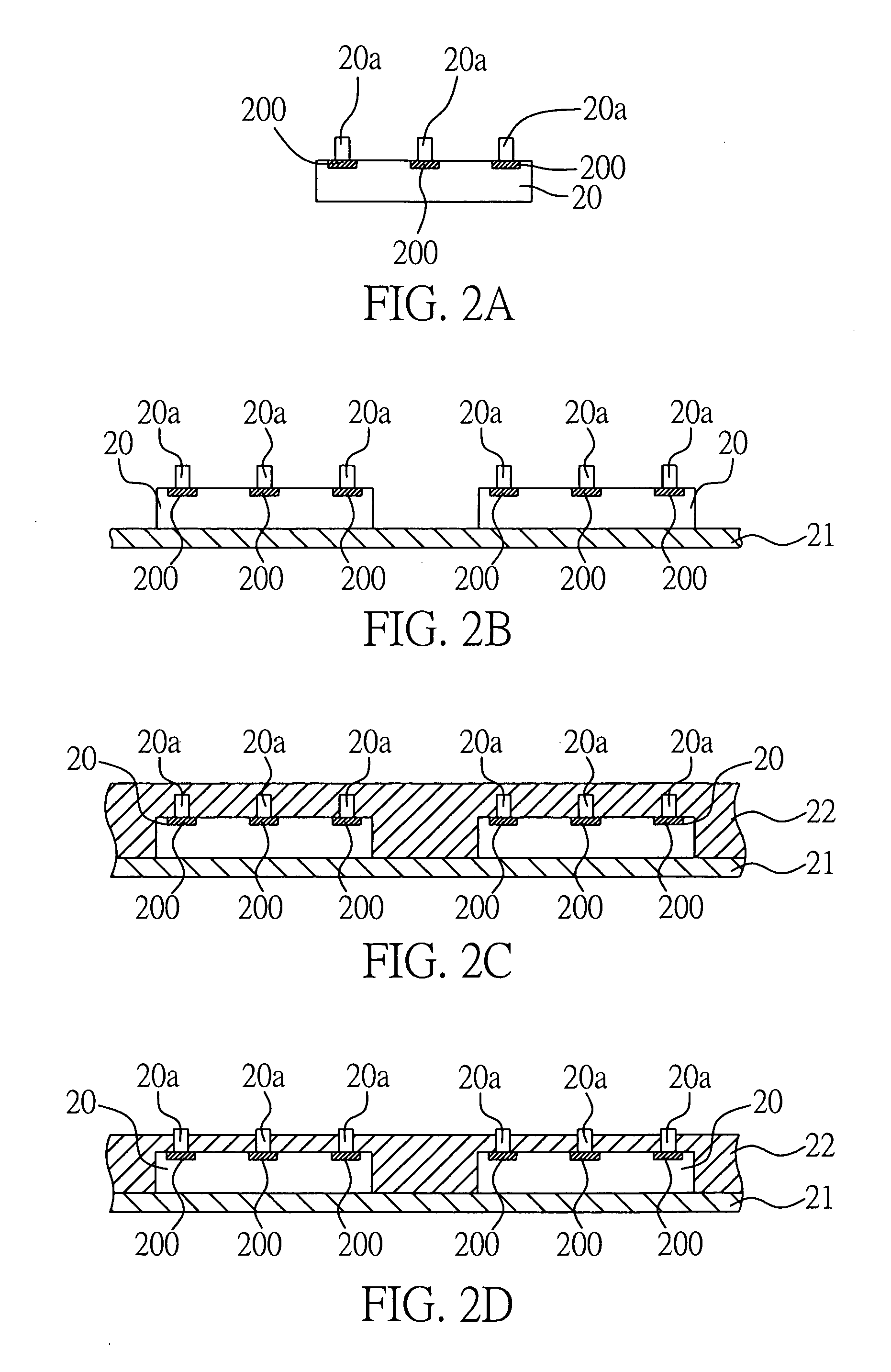
[0021] Preferred embodiments of a semiconductor chip electrical connection structure proposed in the present invention are described in detail as follows with reference to FIGS. 2A to 2G and FIGS. 3A to 3C.
[0022]FIGS. 2A to 2G are cross-sectional schematic diagrams showing procedural steps of a method for fabricating a semiconductor chip electrical connection structure according to the present invention.
[0023] As shown in FIG. 2A, one or more chips 20 each having electrode pads 200 thereon are provided, with a plurality of conductive bumps 20a being formed on the electrode pads 200 respectively. The conductive bump 20a can be made of a conductive metal selected from the group consisting of copper (Cu), gold (Au), silver (Ag), tin (Sn), nickel (Ni) and palladium (Pd), or comprises a plurality of layers made of the foregoing metals. In practice, the conductive bump 20a is preferably made of, but not limited to, copper (Cu). Further, the conductive bumps 20a can be formed by a techni...
PUM
 Abstract
Description
Claims
Application Information