Image forming process and image forming apparatus

a technology of image forming and forming process, which is applied in electrographic process, instruments, other domestic objects, etc., can solve the problems of high plate cost of individual prints, high production base, and comparatively high price, and achieve the effect of sacrificing the high recording flexibility of ink-jet recording system

Inactive Publication Date: 2006-07-27
CANON KK
View PDF24 Cites 62 Cited by
  • Summary
  • Abstract
  • Description
  • Claims
  • Application Information

AI Technical Summary

Benefits of technology

[0017] It is therefore an object of the present invention to provide an image forming process, which permits recording of an image on a wide variety of recording media irrespective of the ink absorbency of a recording medium used without sacrificing the high recording flexibility of an ink-jet recording system, and an image forming apparatus used for realizing this process.

Problems solved by technology

When the provision of prints of various kinds and small lots has advanced with the diversification of information in recent years, however, a problem that the plate cost to the individual prints becomes high, and so the price is comparatively expensive has arisen.
In addition, since vast equipment investment is required, and operations of all steps requires great skill, the production base is limited, and it takes a long time from completion of the printing and delivery of a print to a customer.
However, the ink-jet recording system is not a little affected by the ink absorbency of a recording medium used, and so it is difficult to record a high-quality image irrespective of the kind of the recording medium.
In particular, it is hard to record a high-quality image on recording media (including non-absorbent recording media that do not absorb an ink at all) poor in ink-absorbing ability.
When recording is conducted on a recording medium poor in ink-absorbing ability, a phenomenon called bleeding that ink droplets which impacted adjacently mix with each other and / or a phenomenon called beading that an ink which impacted previously attracts an ink which impacted subsequently, to cause aggregation of the ink droplets, so that image quality is often deteriorated.
In the above-described reference documents, however, the ability to hold the ink image on the intermediate transfer medium is low, and so beading or bleeding occurs on the intermediate transfer medium like the above-described non-absorbent recording medium.
However, the technique that the flowability of the ink on the intermediate transfer medium can be lowered to make high the ink image on the intermediate transfer medium and also the ink image on the recording medium after the transfer has not been realized by any of the above-described documents.
As a result, the thickness of the ink of an outputted image becomes great, thus leading to deterioration of image quality.
In other words, this system cannot make high the quality of the ink image on the recording medium after the transfer because a sense of incompatibility occurs on the ink image on the recording medium after the transfer due to the great thickness of the ink applied.
In addition, since the ink solid at ordinary temperature is used, the ink within an ink flow path must be heated and melted upon start-up, and so it takes time to output an image.
Further, since there is need of retaining this state during operation, vast energy is required.
Beading or and bleeding cannot be prevented by simply heating the transfer medium like Japanese Patent Application Laid-Open No. 5-330035 because the beading or bleeding of inks occurs before the ink flowability is sufficiently lowered, since the beading or bleeding occurs in the moment at the impact of the inks.
This system only achieves the effect of drying the ink image formed on the transfer medium.
The ability to hold the ink image on the transfer medium is still low, and so the quality of the ink image on the transfer medium cannot be made high, and the quality of the ink image on the recording medium cannot also be made high.
However, the quality of the ink image on the intermediate transfer medium cannot be made high.
As a result, an ink is ejected in such a state that the beading of the reactive liquid has occurred, so that the ink cannot be held at a normal position to fail to make the quality of the ink image on the transfer image high.
However, the ink image sticks to the intermediate transfer medium, so that the ink image cannot be successfully transferred to the recording medium, and moreover cleaning becomes difficult.
As apparent from the above, to form a high-quality ink image on various recording media including recording media (for example, non-absorbent recording media) poor in ink-absorbing ability has not been yet realized without being affected by the ink absorbency of the recording media even by the methods using the intermediate transfer medium.

Method used


Image

  • Image forming process and image forming apparatus
  • Image forming process and image forming apparatus

Examples


first embodiment

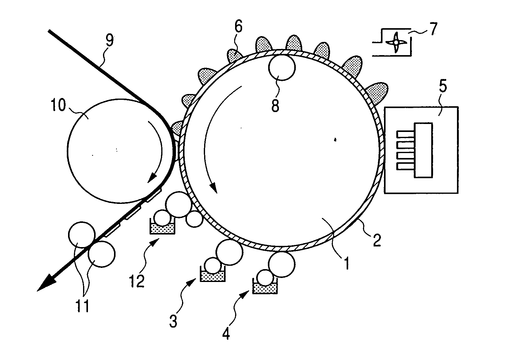
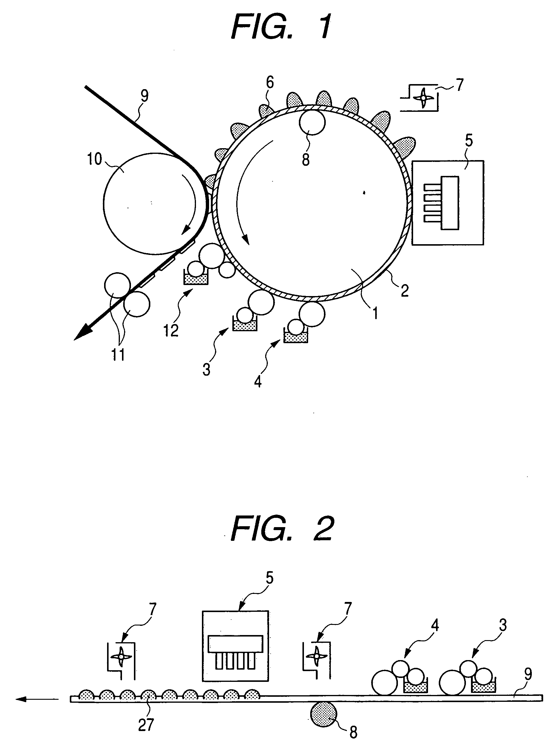
[0050] The feature of the first embodiment of the present invention is first briefly described before this embodiment described in detail. The feature of the first embodiment resides in that a first material (wettability-improving component) for improving the wettability of the surface of an intermediate transfer medium is applied to the intermediate transfer medium before the application of a second material (image-fixing component) for lowering the flowability of an ink on the intermediate transfer medium for the purpose of permitting uniform application of the second material to the intermediate transfer medium or holding of the second material applied to the intermediate transfer medium at a desired position. By applying this first material, the image-fixing component is prevented from being repelled on the intermediate transfer medium, and so the beading of the image-fixing component does not occur. Therefore, the image-fixing component can be uniformly applied to the intermedi...

example 1

[0094] An image-recording system of this example will hereinafter be described by steps.

(a) Application of Wettability-Improving Component:

[0095] In this example, an aluminum drum coated with a silicone rubber (KE12, trade name, product of Shinetsu Kagaku Co., Ltd.) having a rubber hardness of 40° in a thickness of 0.5 mm was used as the intermediate transfer medium. A fluorocarbon type surfactant (FTERGENT FT-400, trade name, product of NEOS Company Limited) was first applied to the surface of the intermediate transfer medium by a roll coater.

(b) Application of Image-Fixing Component:

[0096] A 10% aqueous solution of aluminum chloride hexahydrate was then applied by a roll coater.

(c) Formation of Ink Image:

[0097] A character image mirror-reversed was formed on the intermediate transfer medium, to the surface of which the above components had been applied in Steps (a) and (b), by means of an ink-jet recording apparatus (nozzle density: 1200 dpi; ejection quantity: 4 μl; driv...

example 2

[0099] An image-recording system of this example will hereinafter be described by steps.

(a) Application of Wettability-Improving Component:

[0100] In this example, an aluminum drum coated with a silicone rubber (KE30, trade name, product of Shinetsu Kagaku Co., Ltd.) having a rubber hardness of 60° in a thickness of 0.5 mm was used as the intermediate transfer medium. A fluorocarbon type surfactant (SURFLON S-141, trade name, product of SEIMI CHEMICAL Co. Ltd.) was first applied to the surface of the intermediate transfer medium by a roll coater.

(b) Application of Image-Fixing Component:

[0101] The following aqueous solution was then applied by a roll coater.

Calcium chloride dihydrate10 partsFluorocarbon type surfactant 1 part(SURFLON S-141, trade name, productof SEIMI CHEMICAL Co. Ltd.)Crosslinking agent (Carbodilite V-02, 1 partTrade name, product of NisshinboCo. Ltd.)Ion-exchanged water88 parts.

(c) Formation of Ink Image:

[0102] A character image mirror-reversed was formed...


PUM

PropertyMeasurementUnit
contact angleaaaaaaaaaa
critical surface tensionaaaaaaaaaa
thicknessaaaaaaaaaa

Abstract

Disclosed herein is an image forming process comprising the steps of applying a first material for improving the wettability of the surface of an intermediate transfer medium to the intermediate transfer medium, applying a second material for lowering the flowability of an ink to the intermediate transfer medium to which the first material has been applied, applying the ink to the intermediate transfer medium, to which the first material and second material have been applied, from an ink-jet recording head to form an image of the ink on the intermediate transfer medium, and transferring the ink image formed to a recording medium.

Description

TECHNICAL FIELD [0001] The present invention relates to an image forming process and an image forming apparatus using an ink-jet recording system, and particularly to an image forming process hard to be affected by the ink absorbing quantity of a recording medium used and an image forming apparatus used for realizing this process. BACKGROUND ART [0002] At present, the formation of an image using paper as a recording medium is mainly performed by offset printing. The offset printing is suitable for mass production because it can provide high-quality prints at high speed, and the production cost per sheet can be greatly reduced because of the mass production. The reason for it is that once a plate is fabricated by a plate-making step, a great number of reproductions can be made on the basis of this plate, and so the proportion of plate making cost required of individual prints can be lessened. Such offset printing has well matched with the needs of the market to date. [0003] When the ...

Claims


Application Information

Patent Timeline
Patent Type & Authority Applications(United States)
IPC IPC(8): B41J2/01B41M5/00
CPCB41M5/0256Y10T428/24802B41P2227/70
Inventor TANIUCHI, HIROSHIMOURI, AKIHIRO
Owner CANON KK
Why Eureka
Try Eureka