
Reinforcement member, method of manufacturing reinforcement member, and engine block

a technology of reinforcement member and reinforcement block, which is applied in the direction of crankshaft bearings, machines/engines, animal housings, etc., can solve the problems of restricted engine performance, noise and vibration increase, expansion is inhibited, etc., and achieves low thermal expansion, light weight, and high strength.

Inactive Publication Date: 2006-07-27
NHK SPRING CO LTD
View PDF12 Cites 1 Cited by
  • Summary
  • Abstract
  • Description
  • Claims
  • Application Information

AI Technical Summary

Benefits of technology

[0018] In the present invention, a hollow portion is provided in a reinforcing member which is integrally cast with a cast product, so that the reinforcing member can have light weight and low thermal expansion. Since the reinforcing member and the cast metal are difficult to separate from each other, the cast product can have high strength. In production for the reinforcing member, since the main member can be formed by punching out it without special processing, the production cost can be low.

Problems solved by technology

This is because in the case in which there is a difference in thermal expansion rate among members of the engine block, engine performance is restricted due to undesirable stress generated in the engine block when the temperature of the engine is increased.
Due to this, as the temperature of the engine increases, a gap is formed between the journal portion and the crank shaft, so that noise and vibration increase during high speed rotation thereof.
However, in the techniques disclosed in Patent Documents 1 to 3, there are the following problems which need to be overcome.
In the technique disclosed in Patent Document 1, the thermal expansion is inhibited but the adhesion characteristic between the aluminum alloy material and the iron material which is as the reinforcing material is not good, and the iron material peels from the aluminum alloy material.
Due to this, the obtained material has low strength as a composite material, and the thermal expansion inhibition effect is decreased by the peeling.
As a result, when the obtained material is used for a structure of a journal portion, noise and vibration are easily generated.
Since an iron material is used, the obtained material is heavy, so that this is undesirable to reduce weight.
In the technique disclosed in Patent Document 2, although the adhesion characteristic between the aluminum alloy material and the iron material which is as the reinforcing material is increased, the production cost is high since plating processing and annealing processing are further required.
In the technique disclosed in Patent Document 3, the metal based composite material is required to be separately produced, and heating processing therefore is required, so that the production cost is high.

Method used


Image

  • Reinforcement member, method of manufacturing reinforcement member, and engine block
  • Reinforcement member, method of manufacturing reinforcement member, and engine block
  • Reinforcement member, method of manufacturing reinforcement member, and engine block

Examples


embodiment

3. Test Results of Embodiment

[0038]FIG. 3 is a perspective view showing a cast test body produced by using the reinforcing member 101 of the embodiment. The cast test body shown in FIG. 3 was obtained as follows. FIG. 6 is a top view showing a size of the iron plate 105 of the reinforcing member 101 integrally cast with a cast test body 110.

[0039] After the reinforcing member 101 was obtained, the reinforcing member 101 was disposed in a casting die. Melted aluminum having a temperature of 750 degrees C. was poured thereinto at a casting pressure of 100 MPa, so that the cast test body 110 which was composed of aluminum and was reinforced by the reinforcing member 101 was obtained. This cast test body 110 was structured such that overall peripheral surfaces were covered with an aluminum material. The above casting was performed such that the surface of the reinforcing member at a hole portion 113 described hereinafter was covered with the aluminum material having a thickness of 2 mm...

application of embodiment

[0045]FIG. 5 is a portion of an engine block for automobiles using an example of the reinforcing member of the present invention. A portion 120 of an engine block for automobiles of this example is equipped with five journal portions 122. A reinforcing member 121 of the present invention is integrally cast with each journal portion 122. For example, the portion 120 of the engine block is composed of aluminum alloy. In the structure of this example, since the journal portions 122 for receiving a crank shaft are reinforced by the reinforcing member, and the thermal expansion rate is reduced, a light engine block which endures speed rotation and heavy action is provided. Metal (not shown in the Figure) is further applied to the surface of each journal portion 122 for receiving the crank shaft, and functions as a bearing.


PUM

PropertyMeasurementUnit
diameteraaaaaaaaaa
thicknessaaaaaaaaaa
pressureaaaaaaaaaa

Abstract

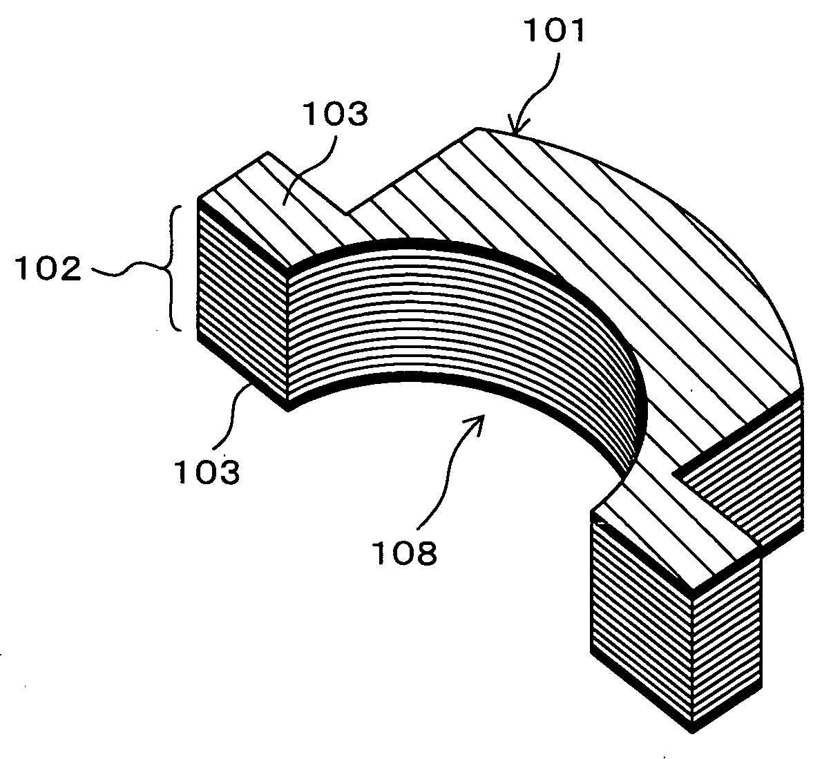
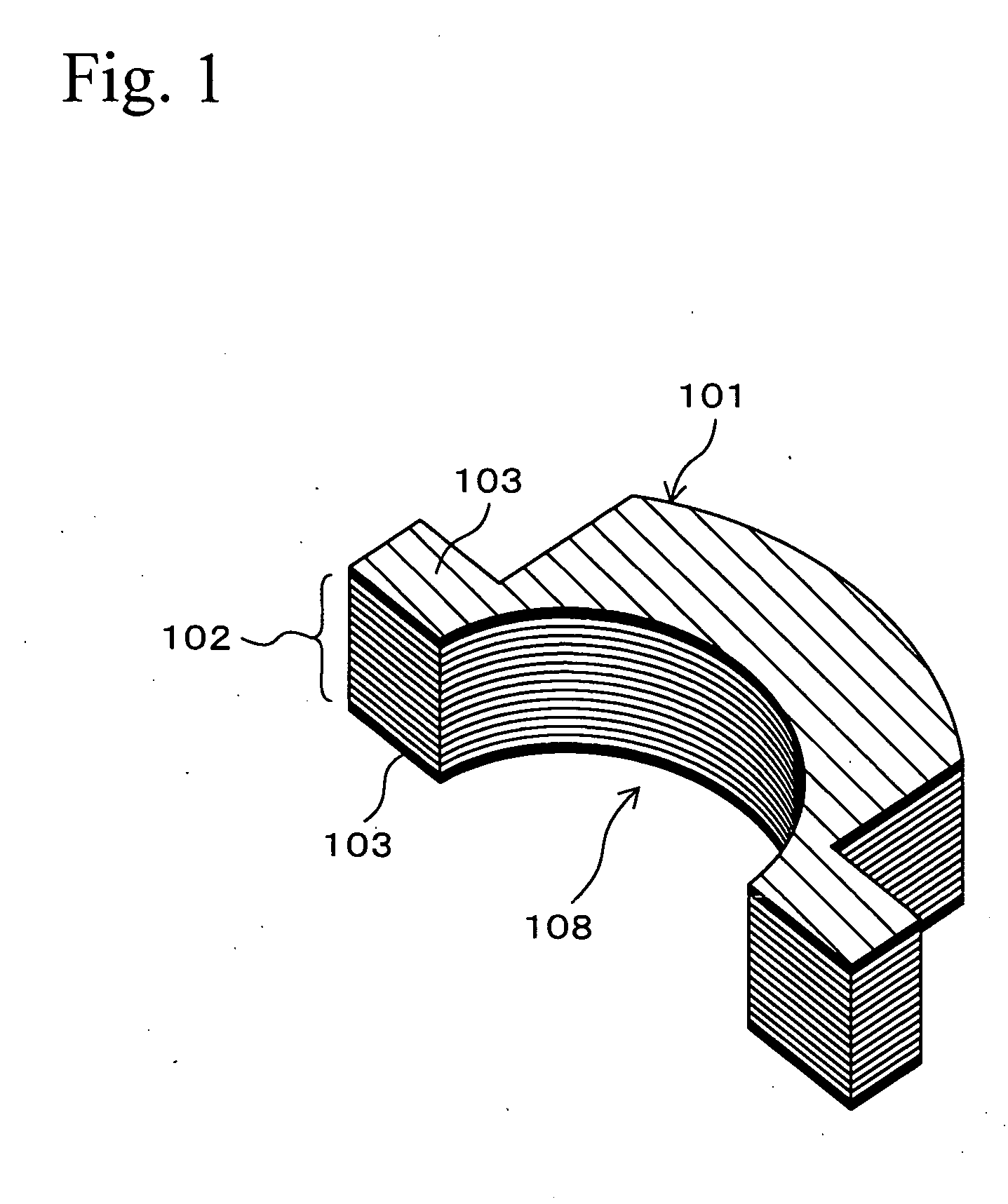
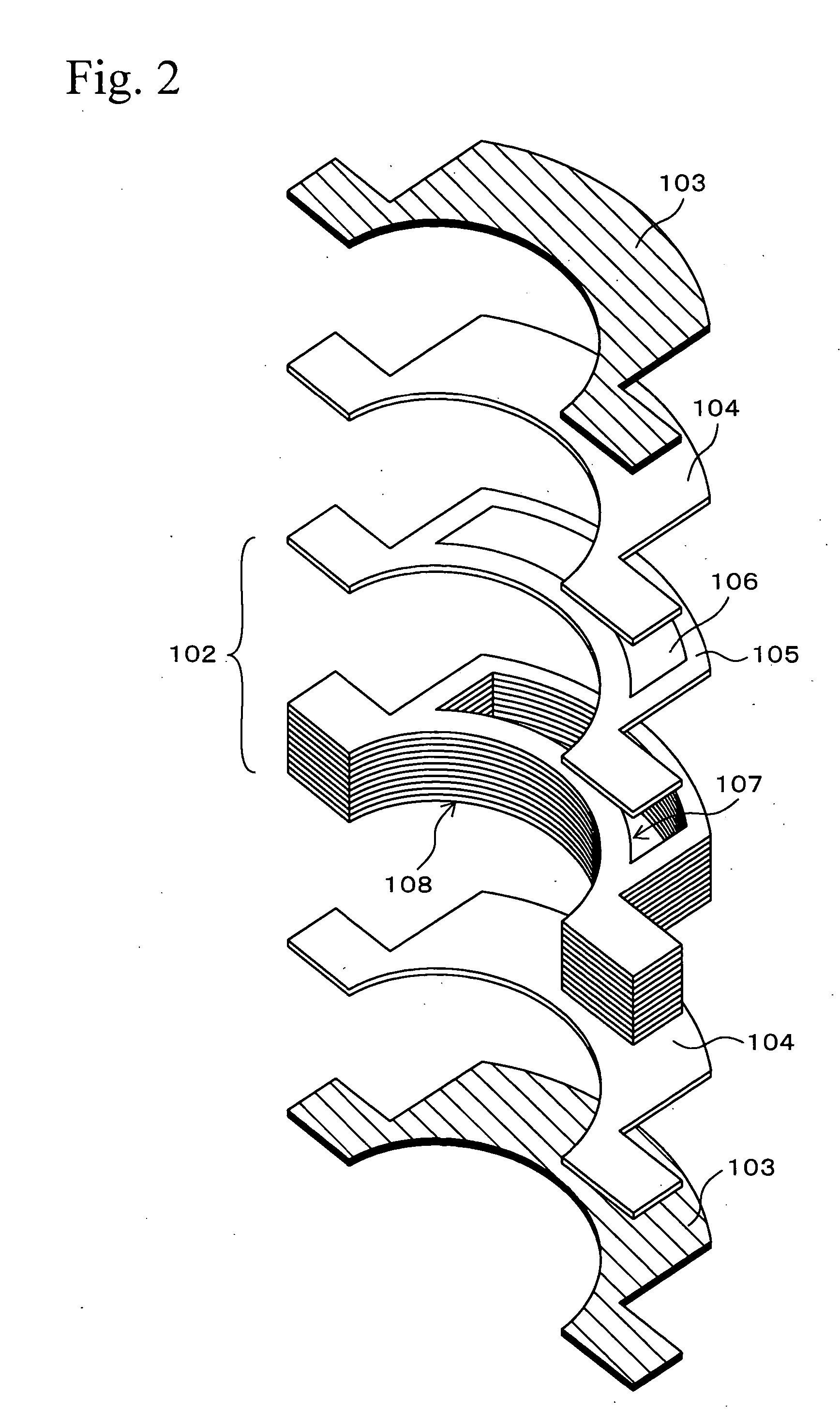
A portion of a reinforcing member has a stacked structure 102 in which plural iron plates having openings 106 are stacked. A hollow portion 107 is formed inside the stacked structure 102, so that the reinforcing member is reduced in weight. Porous bodies 103 composed of non-woven fabric of metal fibers are disposed on surfaces contacting matrixes, so that adhesion between the reinforcing member and the matrix is improved, and peeling therebetween is prevented. A cast product which is composed of light metal and has the above reinforcing member has a small thermal expansion. For example, the cast product is desirable for use for a journal portion of an engine block.

Description

TECHNICAL FIELD [0001] The present invention relates to a reinforcing member for reinforcing light metals used for automobile parts and airplane parts or the like. BACKGROUND ART [0002] In many fields of automobile parts and airplane parts, etc., aluminum alloys are used to reduce weight. Aluminum alloys are superior in weight reduction, but thermal expansions thereof are large when the aluminum alloys are exposed to high temperatures. [0003] For example, a technique is known in which an engine block for automobile engines is composed of an aluminum alloy to reduce weight. The engine block has a journal portion (journal bearing portion) for supporting a crankshaft. [0004] As described above, in the case in which the engine block is composed of aluminum alloy to reduce weight, the journal portion is desirably composed of an aluminum alloy. This is because in the case in which there is a difference in thermal expansion rate among members of the engine block, engine performance is rest...

Claims


Application Information

Patent Timeline
Patent Type & Authority Applications(United States)
IPC IPC(8): A01K1/015B28B1/14B32B3/26B22D19/00B22D19/08F02F7/00B22D19/14C22C47/12F16C9/02F16C33/14F16F15/02
CPCB22D19/14Y10T428/12493F16C33/14F16C9/02F16C2220/20F16C2223/32F16C2220/82F16C2226/34Y10T428/249953Y10T428/249927Y10T428/249921Y10T428/249955Y10T428/249971C22C21/00
Inventor SHIRAISHI, TORUKATSUYA, AKIHIRO
Owner NHK SPRING CO LTD
Learn More