Fuel cell system ensuring stability of operation

a fuel cell and stability technology, applied in the field of fuel cell systems, can solve the problems of the decrease in the apparent concentration of oxygen in the whole air supplied to the fuel cell, and achieve the effects of increasing the apparent concentration of oxygen, increasing the concentration of oxygen in the air, and reducing the amount of water vapor contained

Inactive Publication Date: 2006-07-27
DENSO CORP
View PDF1 Cites 21 Cited by
  • Summary
  • Abstract
  • Description
  • Claims
  • Application Information

AI Technical Summary

Benefits of technology

[0008] In order to alleviate the above problems, the inventor of this application studied a fuel cell system designed to supply non-humidified air to fuel cells to increase the concentration of oxygen in the air. The fuel cell system works to decrease the amount of water vapor contained in the air to be supplied to the fuel cells to increase the apparent concentration of oxygen in the air based on the fact that water vapor contained in air causes the apparent concentration of oxygen in the whole of the air to decrease.

Problems solved by technology

Such systems, however, have two problems, as discussed below.
The second problem is that the water, as produced by the power generation of the fuel cells, is evaporated and mixed with the air, thereby resulting in a decrease in apparent concentration of oxygen in the whole of the air supplied to the fuel cells.

Method used


Image

  • Fuel cell system ensuring stability of operation
  • Fuel cell system ensuring stability of operation
  • Fuel cell system ensuring stability of operation

Examples


first embodiment

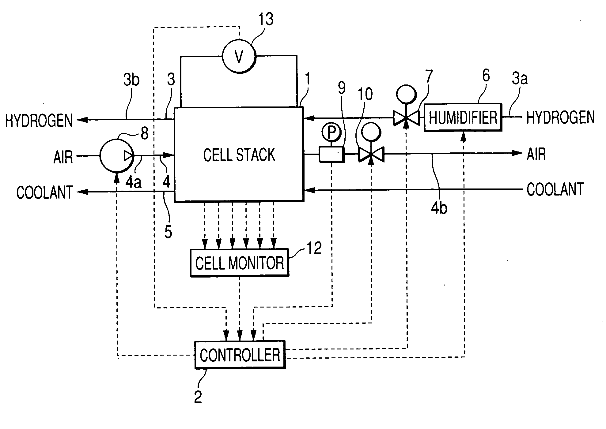
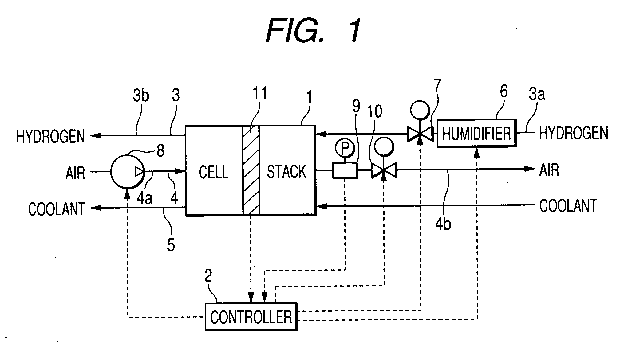
[0067] Referring to the drawings, wherein like reference numbers refer to like parts in several views, particularly to FIG. 1, there is shown a fuel cell system according to the invention which is designed to increase the pressure of air in air flow paths extending in fuel cells higher than that when the fuel cells are operating normally, thereby keeping the fuel cells in desired operating conditions.

[0068] The fuel cell system consists essentially of a fuel cell stack 1, a controller (ECU) 2, a hydrogen path 3, an air path 4, and a coolant path 5. The fuel cell stack 1 is made up of, for example, a plurality of solid polymer electrolyte (proton exchange membrane) fuel cells, as will be described later in detail.

[0069] The hydrogen path 3 includes a hydrogen supply line 3a through which hydrogen gas is supplied to the fuel cell stack 1 and a hydrogen drain line 3b through which the hydrogen gas is drained out of the fuel cell stack 1.

[0070] The fuel cell system also includes a typ...

third embodiment

[0172] Instead of the air pressure regulator valve 10, the throttle 14, as described in the third embodiment, may alternatively be used to regulate the difference between the pressure of the air in the air drain line 4b and the pressure of the hydrogen gas in the hydrogen supply line 3a.

[0173]FIG. 10 shows a fuel cell system according to the fifth embodiment of the invention which is a modification of the fourth embodiment, as illustrated in FIG. 7. The same reference numbers as employed in the fourth embodiment refers to the same parts, and explanation thereof in detail will be omitted here.

fourth embodiment

[0174] The controller 2 of the fuel cell system of the fourth embodiment, as described above, works to elevate the pressure of the air in the air flow path 24 above that of the hydrogen gas in the hydrogen flow path 23 of each of the cells 20 to transfer the water from the air flow path 24 to the hydrogen flow path 23, but it is designed in this embodiment to make a determination of whether the pressure of the air in the air flow path 24 should be elevated or not based on the voltage appearing at each of the cells 20 or the total voltage developed across the fuel cell stack 1.

[0175] The fuel cell system includes a current sensor 44 which measures a total current, as produced by all of the cells 20 of the fuel cell stack 1, and outputs a signal indicative thereof to the controller 2.

[0176] The controller 2 is designed to perform a water-removing program that is similar to the one of FIG. 9 except as described below.

[0177] First, in step 51, the controller 2 samples an output from t...


PUM

PropertyMeasurementUnit
pressureaaaaaaaaaa
pressureaaaaaaaaaa
impedanceaaaaaaaaaa

Abstract

A fuel cell system designed to supply non- or low-humidified air to a fuel cell stack and ensure the stability of operation thereof. The system works to monitor operating conditions of the fuel cell stack and determine whether electrolyte films of fuel cells are getting dried or not or whether an undesirable quantity of water has been produced on the side of air electrodes of the cells or not. When either condition is true, the system works to elevate the pressure of air in an air drain line of the fuel cell stack to enhance the production of water in the cells to keep the electrolyte films or-to transfer the water from the air electrodes to the fuel electrodes of the cells to keep the electrolyte films in a desired wet condition, thereby ensuring the stability of operation of the fuel cell stack.

Description

CROSS REFERENCE TO RELATED DOCUMENT [0001] The present application claims the benefit of Japanese Patent Application No. 2005-17056 filed on Jan. 25, 2005 the disclosure of which is incorporated herein by reference. BACKGROUND OF THE INVENTION [0002] 1. Technical Field of the Invention [0003] The present invention relates generally to a fuel cell system designed to ensure the stability of operation thereof. [0004] 2. Background Art [0005] Typical fuel cells designed to generate electrical energy through electrochemical reactions between oxidant and fuel gas are generally supplied with air as the oxidant and hydrogen gas as the fuel gas. An output of the fuel cells depends upon the concentration of oxygen contained in air. The improvement of the output of the fuel cells is, therefore, achieved by increasing the concentration of oxygen in the air to be supplied to the fuel cells. [0006] For example, Japanese Patent First Publication Nos. 2003-229165 and 10-321249 (equivalent to U.S. P...

Claims


Application Information

Patent Timeline
Patent Type & Authority Applications(United States)
IPC IPC(8): H01M8/04H01M8/24
CPCH01M8/04089H01M8/04104H01M8/04179H01M8/04328H01M8/0435H01M8/04395H01M8/0441H01M8/04582H01M8/04589H01M8/04708H01M8/04753H01M8/04835H01M8/242Y02E60/50H01M8/241Y02P70/50
Inventor KUDO, HIROYASU
Owner DENSO CORP
Why Eureka
Try Eureka