Exhaust gas purifying apparatus and method for controlling it

a technology of exhaust gas purification apparatus and purification method, which is applied in mechanical apparatus, machines/engines, separation processes, etc., can solve the problems of low purification efficiency of catalysts, high exhaust gas temperature of catalysts, and difficult to meet a demanded purification level only with the use of catalysts, etc., to prevent the production of unsaturated hydrocarbons, accelerate cracking and reforming, and suppress the generation of soot

Inactive Publication Date: 2006-06-01
CRYOQUIP +1
View PDF13 Cites 19 Cited by
  • Summary
  • Abstract
  • Description
  • Claims
  • Application Information

AI Technical Summary

Benefits of technology

[0040] In the case where a recirculated exhaust gas is converted into a plasma with an addition of water, OH (hydroxy) radical, an O (oxygen) radical, etc. obtained by converting water into a plasma accelerates cracking and reforming; and is bonded to the terminal of a reducing agent molecular chain broken by the plasma, thereby preventing production of an unsaturated hydrocarbon or suppressing the generation of soot.
[0041] Further, according to the controlling method described in (5) or (11) above, by converting air into a plasma without a reducing agent being added by the injector when an oxidizing condition is satisfied, a highly oxidative content such as an oxygen radical, ozone, etc. can be effectively produced. This is because air has a higher oxygen concentration than a recirculated exhaust gas.

Problems solved by technology

However, as the regulations regarding exhaust gases are becoming stricter, it is becoming difficult to satisfy a demanded purification level only with the use of a catalyst.
Further, purification with a catalyst needs a high exhaust gas temperature and the purification efficiency with a catalyst may be low at the beginning of a purification process.
However, the restrictions regarding purification of an exhaust gas are becoming stricter from year to year, and further improvements in an exhaust gas purifying apparatus are demanded.

Method used


Image

  • Exhaust gas purifying apparatus and method for controlling it
  • Exhaust gas purifying apparatus and method for controlling it
  • Exhaust gas purifying apparatus and method for controlling it

Examples


Embodiment Construction

[0059] The present invention is specifically described below based on the embodiments shown in the Figures. Each Figure is a view for showing the concept of the present invention but the present invention is not limited to the embodiments.

[0060]

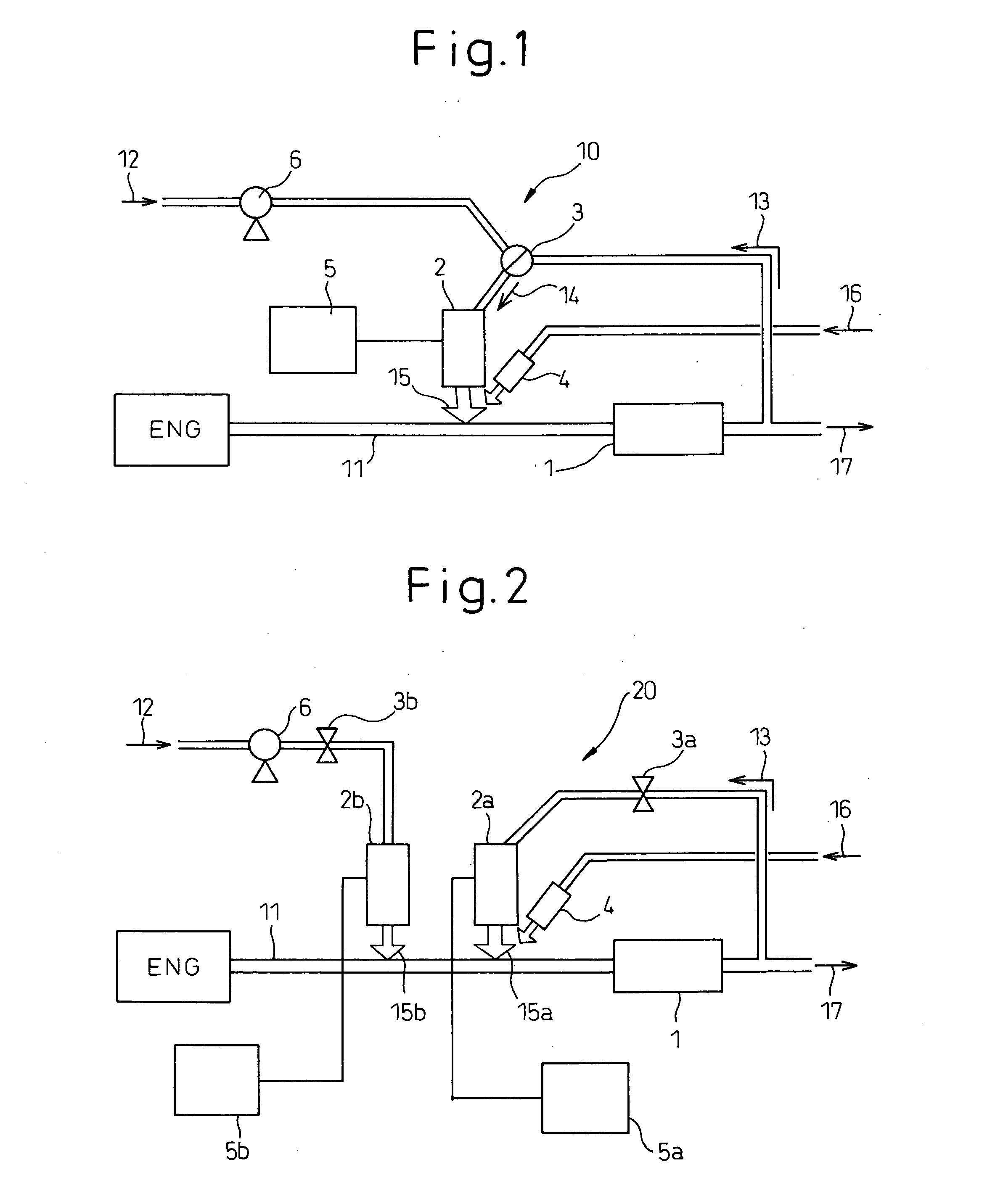
[0061]FIG. 1 schematically shows one embodiment of the exhaust gas purifying apparatus of the present invention.

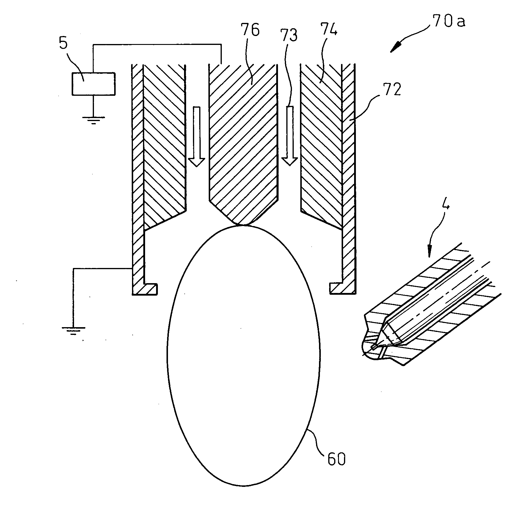
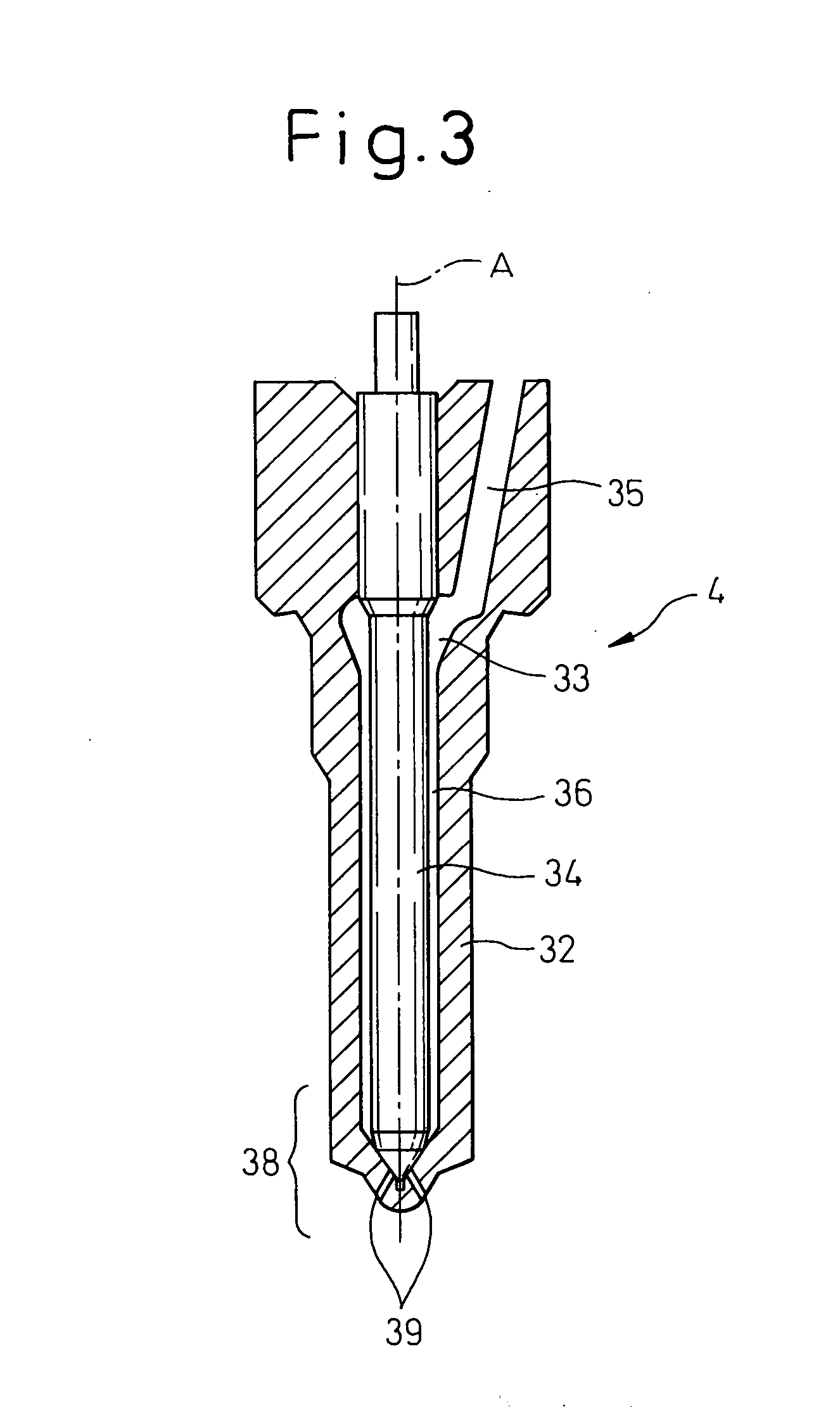
[0062] As shown in FIG. 1, the exhaust gas purifying apparatus of the present invention 10 comprises a NOx purifying catalyst 1 disposed in an exhaust gas pipe 11 for an internal combustion engine (ENG); a plasma generator 2 for converting a gas (arrow 14) into a plasma and supplying the plasma to the exhaust pipe 11 at the upstream of the NOx purifying catalyst 1; a switching device 3 for selectively supplying one of a recirculated exhaust gas (arrow 13) and air (arrow 12) to the plasma generator 2; and an injector 4 for adding a reducing agent (arrow 16) to the gas (arrow 14) to be supplied to the plasma generator 2 or a plasma ...


PUM

PropertyMeasurementUnit
pulse voltageaaaaaaaaaa
electric currentaaaaaaaaaa
voltageaaaaaaaaaa

Abstract

The present invention provides an exhaust gas purifying apparatus 10 which can effectively purify an exhaust gas with the use of a plasma. The present exhaust gas purifying apparatus 10 comprises a NOx purifying catalyst 1 disposed in an exhaust gas pipe 11 for an internal combustion engine (ENG); a plasma generator 2 for converting a gas into a plasma and supplying the plasma to the exhaust pipe at the upstream of the NOx purifying catalyst; a switching device 3 for selectively supplying one of a recirculated exhaust gas 13 and air 12 as a gas to be converted into a plasma to the plasma generator 2; and an injector 4 for adding a reducing agent to the gas 14 to be converted into a plasma or a plasma 15 converted from the gas by the plasma generator. The present invention further provides a method for controlling the exhaust gas purifying apparatus.

Description

TECHNICAL FIELD [0001] The present invention relates to an exhaust gas purifying apparatus and a method for controlling it and, particularly, to an exhaust gas purifying apparatus for purifying an exhaust gas from an internal combustion engine and a method for controlling it. RELATED ART [0002] Exhaust gases, e.g. from automobiles, garbage incineration plants, etc., are generally discharged to the atmosphere after being purified mainly with use of catalysts. However, as the regulations regarding exhaust gases are becoming stricter, it is becoming difficult to satisfy a demanded purification level only with the use of a catalyst. Further, purification with a catalyst needs a high exhaust gas temperature and the purification efficiency with a catalyst may be low at the beginning of a purification process. [0003] In order to solve the problems associated with the use of a catalyst, various systems utilizing a plasma generated by an electric discharge have been proposed. In particular, ...

Claims


Application Information

Patent Timeline
Patent Type & Authority Applications(United States)
IPC IPC(8): C01B31/00B01J19/08
CPCB01D53/9431B01D53/9495B01D2259/818F01N3/023F01N3/0275F01N3/035F01N3/0814F01N3/0842F01N3/0892F01N3/2066F01N2240/28F01N2570/14F01N2610/03F01N2610/08H05H1/24Y02T10/24F01N13/009Y02A50/20Y02T10/12H05H1/47H05H2245/15H05H1/34
Inventor HIRATA, HIROHITOISHIBASHI, KAZUNOBU
Owner CRYOQUIP
Why Eureka
Try Eureka