Arrangement for the optoelectronic recording of large-area fingerprints

an optoelectronic and fingerprint technology, applied in the field of optoelectronic recording of large-area fingerprints, can solve the problems of difficult evaluation, inability to reliably achieve the quality necessary for applications of this kind, and inability to correctly gather the output imag

Inactive Publication Date: 2006-08-03
CROSS MATCH TECH
View PDF12 Cites 20 Cited by
  • Summary
  • Abstract
  • Description
  • Claims
  • Application Information

AI Technical Summary

Benefits of technology

[0015] It is the primary object of the invention to find a novel possibility for recording the papillary ridge pattern of a hand which permits a complete optoelectronic image recording with one-time placement of the print surfaces of a hand without the use of illumination beam paths or imaging beam paths that are inadequately sealed against environmental influences and without having to accept a loss of resolution or an appreciably increased expenditure on electronics for rectification of the image recordings and with a support surface that is curved in an ergonomically advantageous manner.

Problems solved by technology

These solutions are directed to arrangements which are either limited in format and allow only part of the palm to be acquired in one process or which can acquire the entire full-size hand but do not reliably achieve the quality necessary for applications of this kind.
In this arrangement, it works out disadvantageously that the palm of the hand is more or less curved inwardly and for this reason does not make direct contact in its entirety with the recording surface so that relatively large areas (usually in the center of the palm) are not imaged (i.e., appear white or empty).
However, given the concave surface of the hand, this improves the imaging only to a certain extent because the increased contact pressure on the parts of the hand that already had good contact before presses the papillary ridges together and the pressed areas in the resulting image appear very dark with poor contrast and are therefore more difficult to evaluate.
It is disadvantageous that the papillary ridges are made visible and imaged using the principle of scattered light because residues from perspiration excreted by the hand must be meticulously removed in their entirety after every placement of the hand so that scattered light from old prints is not detected again.
However, when the hand is moved too quickly over the cylindrical surface, i.e., when the angular velocity exceeds a maximum permissible velocity, the signal processing means of the image sensor are incapable of supplying image data so as to be synchronized with the rotating movement and, consequently, the output image is also not assembled correctly.
For this reason, very complex additional arrangements are provided for measuring the angular velocity and for braking the cylinder when its given rotational speed is exceeded.
Another basic problem consists in that the palm must be moved exactly without relative movement between the palm and the cylinder surface in order to avoid drastic errors in assembling the output image.
With regard to practical realization further disadvantages consist in that there are considerable difficulties in sealing the optical light paths at both end faces of the rotatable cylinder in the transition to the prisms for preventing malfunction due to dust and moisture.
This means that technical expenditure is considerably higher; otherwise, only a lower image quality (resolution in dpi) can be realized in the output image.

Method used


Image

  • Arrangement for the optoelectronic recording of large-area fingerprints
  • Arrangement for the optoelectronic recording of large-area fingerprints
  • Arrangement for the optoelectronic recording of large-area fingerprints

Examples


Embodiment Construction

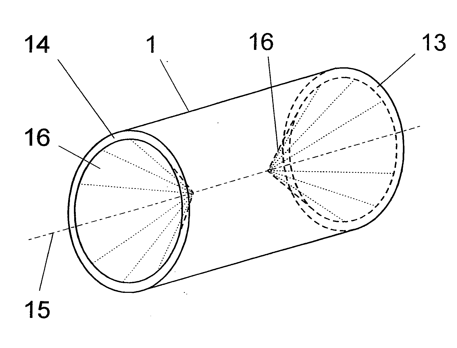
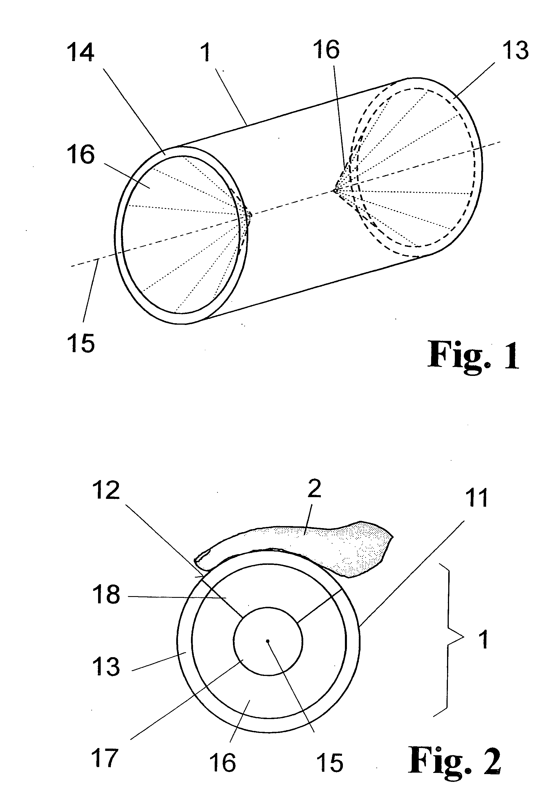
[0046] As regards its basic construction, the invention contains, as the core of the optoelectronic recording device, a specially constructed optically transparent support body as is shown in FIG. 1 for recording large-area prints of skin parts of the fingers 21 or of the entire hand 2 (only in FIG. 2). This cylindrical support body 1 is made of optical material (glass or plastic) in which at least a portion of the outer surface area 11 is provided as a support surface 12 for the hand 2 in such a way that the concave palm of the hand snugly contacts the outer surface 11 of the scanning body 1.

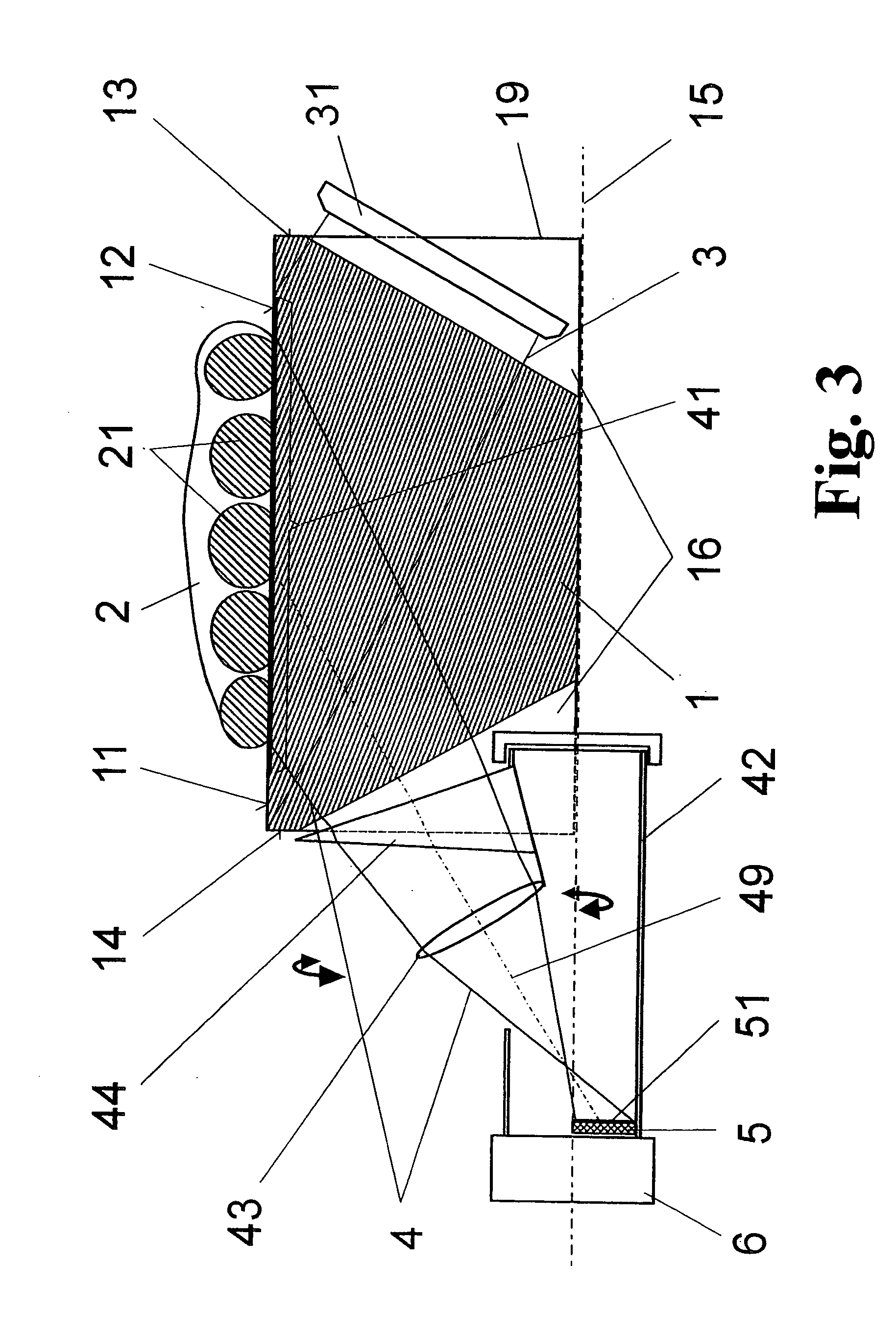
[0047] Conical recesses 16 are arranged coaxial to the cylinder axis 15 in the two end faces 13 of the body 1 for coupling in the illumination beam path 3 on the one hand and for coupling out the imaging beam path 4 on the other hand so that the frustrated (because of the hand placed thereon) total reflection (FTIR) of a strip 41 (see FIG. 9 or FIG. 10) along a lateral line of the outer surfac...


PUM


Abstract

The invention is directed to an arrangement for the optoelectronic recording of large-area fingerprints, particularly for acquiring prints of the entire palm of the hand. The object of the invention is to find a novel possibility for recording the papillary ridge pattern of a hand which permits a complete optoelectronic image recording with one-time placement of large-area concave skin parts without the use of optical beam paths that are subject to contamination and without having to accept a loss of resolution. This object is met, according to the invention, in that the support body for supporting the skin parts has the basic shape of a cylinder providing a portion of the outer surface with a sufficient radian measure and radius as support surface, the end faces of the support body are each provided with a conical recess which is arranged coaxially around the cylinder axis in order to couple in an illumination beam path and an imaging beam path through the surface lines of the conical recesses, and the imaging beam path and a linearly extending image sensor are rotatable synchronously around the cylinder axis in order to record successive line-shaped strips of the frustrated total reflection at the illuminated outer surface of the support body with the supported skin part.

Description

CROSS REFERENCE TO RELATED APPLICATIONS [0001] This application claims priority of German Application No. 10 2005 004 640.1, filed Jan. 28, 2005, the complete disclosure of which is hereby incorporated by reference. BACKGROUND OF THE INVENTION [0002] a) Field of the Invention [0003] The invention is directed to an arrangement for the optoelectronic recording of large-area fingerprints, particularly for acquiring prints of the entire palm of the hand. It is used for the recording of personal features for identification services and forensic identification. [0004] b) Description of the Related Art [0005] In law enforcement identification services, fingerprints and handprints of individuals are taken in order to be able to establish their identity. For more than one hundred years, the recording of the patterns of the papillary ridges on the finger and hand has conventionally been carried out by inking the surfaces of the finger or hand and subsequently printing them on paper. With the ...

Claims


Application Information

Patent Timeline
Patent Type & Authority Applications(United States)
IPC IPC(8): B41N1/00
CPCG06K9/00046G06V40/1324
Inventor REINHOLD, BERNDRICHTER, UWEHILLMANN, JUERGEN
Owner CROSS MATCH TECH
Why Eureka
Try Eureka