Corneal implants and methods and systems for placement

a technology of corneal implants and corneal stents, applied in the field of corneal implants, can solve the problems of not being able to tolerate surgery lens implants, not being designed to be biocompatible with the cornea, and not being able to practically use small incision cataract surgery lenses within the corneal pocket. , to achieve the effect of reducing the size or width, and increasing the deformation

Inactive Publication Date: 2006-08-03
SHIUEY YICHIEH
View PDF28 Cites 67 Cited by
  • Summary
  • Abstract
  • Description
  • Claims
  • Application Information

AI Technical Summary

Benefits of technology

[0021] Once the corneal implant is inside the hollow member, the implant mover or other axial pusher is used to engage and push the implant into the corneal pocket. Optionally, the system may further comprise a deformation chamber where the implant is deformed into a shape and size that will fit inside the hollow member. In other preferred aspects, the deformation chamber may contain ridges, protrusions, indentations, or recesses which help to maintain orientation of the corneal implant within the deformation chamber during the deformation process. Optionally, the hollow member is tapered, i.e., narrower at a distal end than at a proximal end. Such tapering allows additional deformation (size or width reduction) of the implant as it is advanced through the hollow member and passes out through a smaller distal opening. The interior of the hollow member may contain ridges, protrusions, indentations, or recesses which help to maintain orientation of the corneal implant as it travels inside of the hollow member. The system for implant placement is designed to allow an implant to be placed into a corneal pocket with an entry incision that is equal or less than one-half of the width of the implant, however, the system can also be used to place an implant through a corneal incision that is greater than one-half of the width of the implant.

Problems solved by technology

These small incision cataract surgery lenses cannot practically be used within a corneal pocket.
Most small incision cataract surgery lens implants are usually too thick to be placed within a corneal pocket.
Finally, the cataract surgery lens implants are not designed to be biocompatible with the cornea and would not be tolerated as corneal implants.
The delivery systems designed for small incision cataract surgery lens implants are not well adapted for use as a delivery system for small incision corneal implants.

Method used


Image

  • Corneal implants and methods and systems for placement
  • Corneal implants and methods and systems for placement
  • Corneal implants and methods and systems for placement

Examples


Embodiment Construction

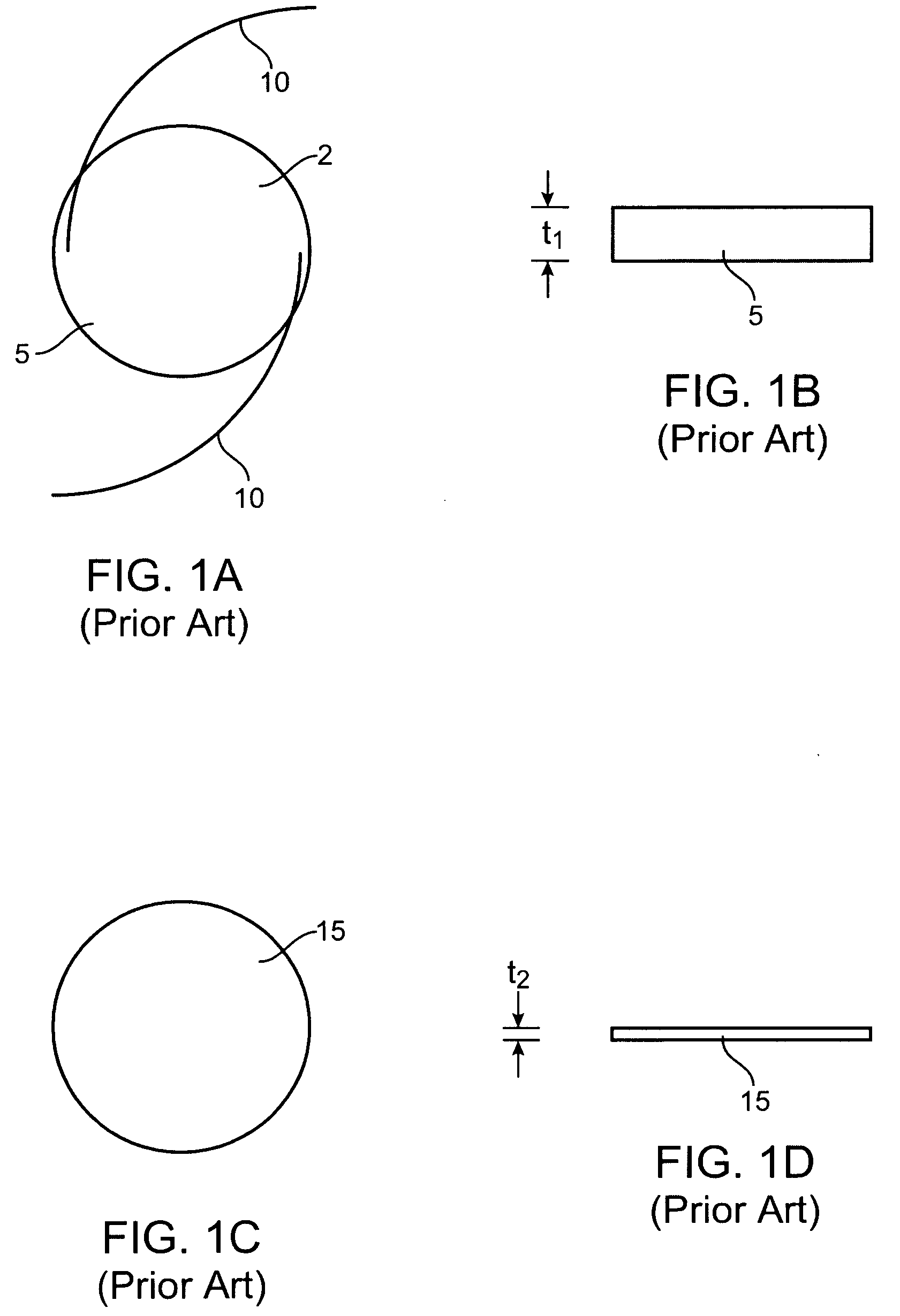
[0034]FIG. 1A shows a top view of a cataract surgery lens implant 2. A round optic 5 of the implant 2 has haptics 10 which extend from the periphery of the optic. The haptics 10 are used to help the optic center and fixate within the capsular bag. FIG. 1B shows a side view of a cataract surgery lens implant optic 5. Note that the thickness t1 of the optic 5 is typically 1 mm or more and is substantially greater than the 0.5 to 0.6 mm thickness of the human cornea. The thickness of the optic 5 makes it inappropriate for use as a corneal lens implant. FIG. 1C shows a top view of a corneal implant 15. Note there are no haptics on the corneal implant. FIG. 1D shows a side view of corneal implant 15. Note that the thickness t2 is substantially less than cataract surgery lens implant 5. The thickness t2 of corneal implant 15 would in general be less than the thickness of the human cornea.

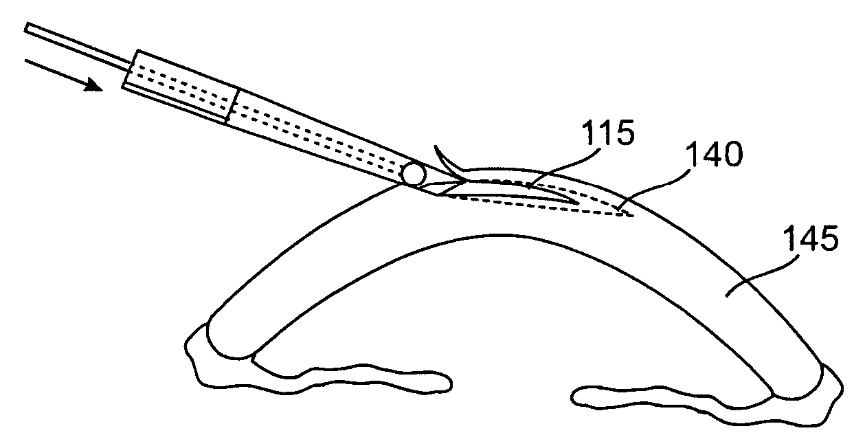
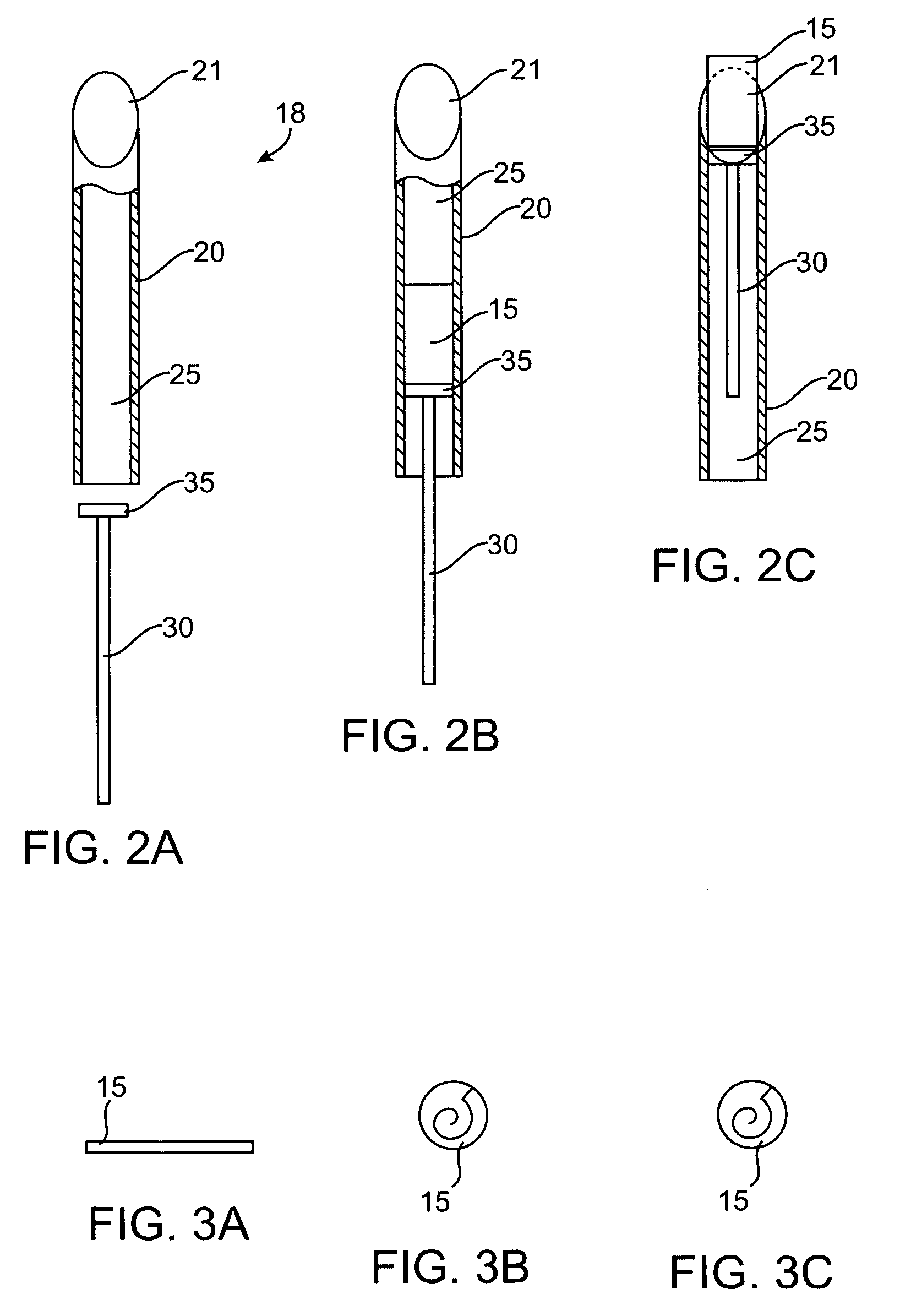
[0035]FIG. 2A shows a corneal implant delivery system 18 in partial section. A hollow member 20 havin...


PUM


Abstract

A system comprising a hollow member is used to deliver a constrained corneal implant into a corneal pocket. The hollow member may be tapered and the system may further include an implant deformation chamber and an axial pusher to advance the implant through the hollow member.

Description

CROSS-REFERENCES TO RELATED APPLICATIONS [0001] The present application is a non-provisional of U.S. Patent Application Ser. No. 60 / 648,949 (Attorney Docket No. 022253-000200US), filed Jan. 31, 2005, the full disclosure of which is incorporated herein by reference.BACKGROUND OF THE INVENTION [0002] 1. Field of the Invention [0003] There are many different types of corneal implants that have been developed for the treatment of refractive error and disease. Because of limitations in the methods of creating corneal pockets, these implants have all been designed for placement in the cornea by creation of a corneal incision which is either similar in size to the smallest dimension of the implant or larger. Recently, two methods of corneal pocket creation have been devised which can create a pocket with an external opening width that is less than the maximum internal width of the pocket. These two methods are pocket creation by the femtosecond laser and, of particular interest, cornea cut...

Claims


Application Information

Patent Timeline
Patent Type & Authority Applications(United States)
IPC IPC(8): A61F2/14
CPCA61F2/142A61F2/146A61F2/145A61F2/143A61F2210/0019A61F2/148A61F2002/16965
Inventor SHIUEY, YICHIEH
Owner SHIUEY YICHIEH
Why Eureka
Try Eureka