
Method for manufacturing electrochemical device

a manufacturing method and electrochemical technology, applied in the manufacture of capacitors, cell components, jackets/cases materials, etc., can solve the problems of inability to reliably mount the electrochemical device of electronic devices, and the failure of the electrochemical device mounting device, so as to ensure the thermal fusion strength, the effect of sufficient mechanical strength and sufficient flexibility

Inactive Publication Date: 2006-08-10
TDK CORPARATION
View PDF1 Cites 5 Cited by
  • Summary
  • Abstract
  • Description
  • Claims
  • Application Information

AI Technical Summary

Benefits of technology

[0014] In view of the above-mentioned problems inherent in the prior art, it is an object of the present invention to provide a method of manufacturing an electrochemical device which can easily and reliably form a case having an excellent sealability even when a lead having a thickness of 0.05 mm or greater with a cross-sectional area of 5.0×10⁻⁴ cm2 or greater is used, while having such an excellent reliability that the leakage can fully be prevented from occurring.
[0045] As a consequence, the bonding state between the metal and the composite package film becomes favorable, and a layer made of the above-mentioned adhesive is formed about the first and second leads, whereby the sealability of the respective seal parts of the first and second films is fully secured in the portions surrounding the first and second leads.

Problems solved by technology

However, the inventors have found that conventional electrochemical devices using a case such as the batteries disclosed in the above-mentioned Patent Documents 1 and 2 are problematic in that they cannot reliably prevent “leakage”, by which an electrolytic solution filling the case leaks out of the case, from occurring when used under a condition which will follow.
When the “leakage” of an electrochemical device occurs, electronic devices mounting the electrochemical device may fail.

Method used


Image

  • Method for manufacturing electrochemical device
  • Method for manufacturing electrochemical device
  • Method for manufacturing electrochemical device

Examples


example 1

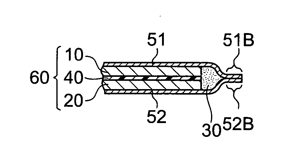
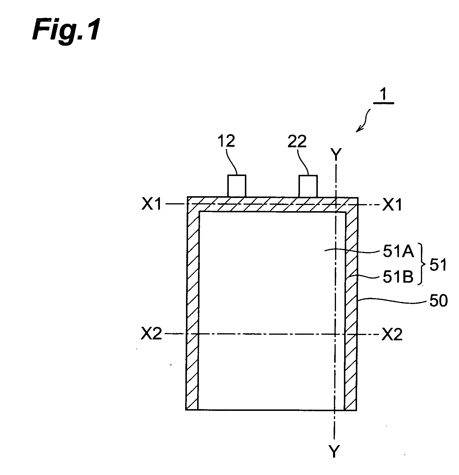
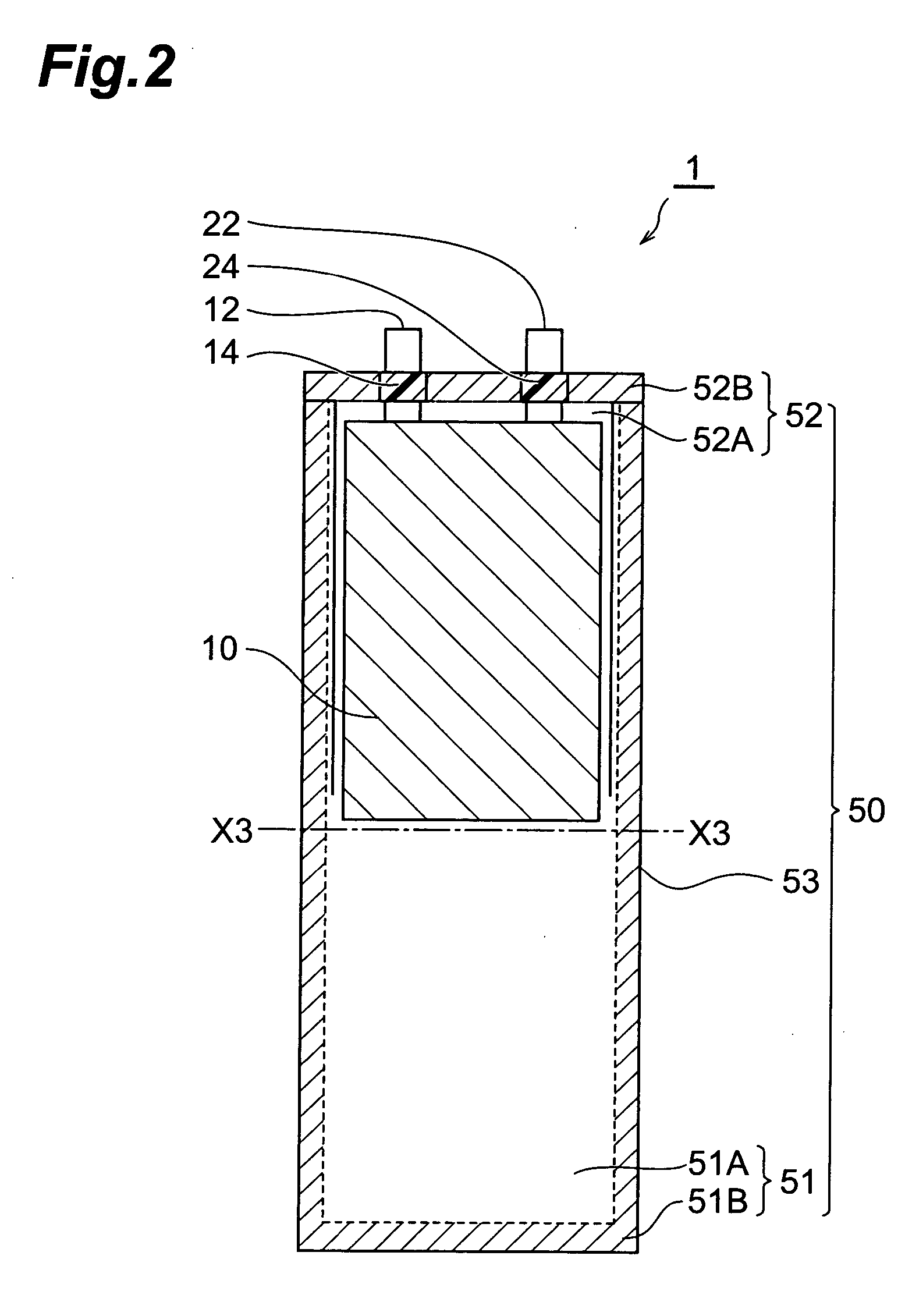
[0145] In the following procedure, an electrochemical capacitor (electric double layer capacitor) having the same configuration as with the electrochemical capacitor shown in FIG. 1 was made.

[0146] (1) Making of Electrode

[0147] An anode (polarizable electrode) and a cathode (polarizable electrode) were made by the following procedure. First, an activated carbon material, a binder (fluorine rubber), and a conductive auxiliary agent (acetylene black) were compounded such that the mass ratio of carbon material / binder / conductive auxiliary agent=80:10:10, and the resulting product was put into MIBK (methyl isobutyl ketone) and kneaded therein, so as to prepare an electrode forming coating liquid (hereinafter referred to as “coating liquid L1”).

[0148] Next, the coating liquid L1 was uniformly applied onto one surface of a collector (having a thickness of 50 μm) made of an aluminum foil (both faces of collectors in electrodes disposed within a matrix since a plurality of anodes, separat...

example 2

[0159] In place of the leads used in Example 1, those having a different thickness (with a width of 10 mm, a length of 25 mm, and a thickness of 3.00 mm) were employed. Accordingly, an electrochemical device was made by the same procedure under the same condition as with the electrochemical device of Example 1 except that the cross-sectional form of the groove 91A of the die 91 used for drawing was a trapezoid (having an upper base of 10.3 mm, a lower base of 10.5 mm, and a height (thickness) of 3.00 mm), and that the cross-sectional form of the groove 93A of the first thermal fusion die 93 used for thermal fusion was a trapezoid (having an upper base of 10.3 mm, a lower base of 10.5 mm, and a height (thickness) of 3.00 mm).

example 3

[0160] In place of the leads used in Example 1, those having a different thickness (with a width of 10 mm, a length of 25 mm, and a thickness of 0.10 mm) were employed. Accordingly, an electrochemical device was made by the same procedure under the same condition as with the electrochemical device of Example 1 except that the cross-sectional form of the groove 91A of the die 91 used for drawing was a trapezoid (having an upper base of 10.3 mm, a lower base of 10.5 mm, and a height (thickness) of 0.10 mm), and that the cross-sectional form of the groove 93A of the first thermal fusion die 93 used for thermal fusion was a trapezoid (having an upper base of 10.3 mm, a lower base of 10.5 mm, and a height (thickness) of 0.10 mm).


PUM

PropertyMeasurementUnit
thicknessaaaaaaaaaa
thicknessaaaaaaaaaa
thicknessaaaaaaaaaa

Abstract

A method of manufacturing an electrochemical device comprising an electrochemical device matrix 60 including first and second electrodes opposing each other; a case, formed by a first film 51 and a second film 52 which oppose each other, for accommodating the electrochemical device matrix in a closed state; a first lead connected to the first electrode; and a second lead connected to the second lead includes a thermal fusion step of thermally fusing the films 51 and 52 to each other while bringing fringes of the films 51 and 52 into contact with each other and pressing the contact portion of the films 51 and 52, whereas a die 93 (heating member) formed with grooves having respective forms in conformity to forms of cross sections of the leads is used at a part where the first and second leads are placed in the contact portion.

Description

TECHNICAL FIELD [0001] The present invention relates to a method of manufacturing an electrochemical device; and, more specifically, to a method of manufacturing an electrochemical device including a secondary battery such as lithium-ion secondary battery. BACKGROUND ART [0002] Electrochemical capacitors such as electric double layer capacitors and nonaqueous electrolyte secondary batteries such as lithium-ion secondary batteries are electrochemical devices which can easily reduce their size and weight, and thus are expected as power supplies or backup power supplies for portable devices (small-size electronic devices) and auxiliary power supplies for electric cars or hybrid cars, for example. [0003] There is a case where the above-mentioned electrochemical devices used as a backup power supply or auxiliary power supply are required to have a function for smoothing the supplied power by rapidly filling the shortage of power when the main power supply cannot sufficiently follow drast...

Claims


Application Information

Patent Timeline
Patent Type & Authority Applications(United States)
IPC IPC(8): B32B37/00H01G9/10H01G13/00H01M50/119H01M50/121H01M50/129H01M50/133H01M50/178H01M50/55H01M50/553H01M50/562H01M50/609
CPCH01G9/10H01G9/155H01M2/021H01M2/0257H01M2/06H01M2/08H01M2/36H01M10/0525H01M10/0585Y02E60/13Y02T10/7011Y02T10/7022Y02T10/70Y02E60/10H01G11/80H01G11/76H01G11/74H01M50/562H01M50/121H01M50/129H01M50/178H01M50/609H01M50/133H01M50/55H01M50/553H01M50/119H01G11/84H01M50/20H01M50/10H01M50/543
Inventor TAKAHASHI, TETSUYA
Owner TDK CORPARATION
Learn More