Method and system for determining flow conditions in a high pressure processing system

a technology of high pressure processing and flow conditions, applied in the direction of liquid cleaning, liquid/solution decomposition chemical coating, instruments, etc., can solve the problems of limiting the use of plasma ashing and many dry cleaning systems lacking the ability to avoid drifting process conditions

Inactive Publication Date: 2006-08-17
TOKYO ELECTRON LTD
View PDF99 Cites 26 Cited by
  • Summary
  • Abstract
  • Description
  • Claims
  • Application Information

AI Technical Summary

Benefits of technology

[0010] A further objective of the invention is to provide a method and system by which a flow condition of the fluid in a high pressure processing system, particularly a supercritical fluid processing system, can be maintained or controlled.

Problems solved by technology

Moreover, the advent of new materials, such as low dielectric constant (low-k) materials, limits the use of plasma ashing due to their susceptibility to damage during plasma exposure.
For instance, many dry cleaning systems lack the ability to avoid drifting process conditions, such as the variation of filter performance due to the accumulation of particles.

Method used


Image

  • Method and system for determining flow conditions in a high pressure processing system
  • Method and system for determining flow conditions in a high pressure processing system
  • Method and system for determining flow conditions in a high pressure processing system

Examples


Embodiment Construction

[0026] In the following description, to facilitate a thorough understanding of the invention and for purposes of explanation and not limitation, specific details are set forth, such as a particular geometry of the processing system and various descriptions of the system components. However, it should be understood that the invention may be practiced with other embodiments that depart from these specific details.

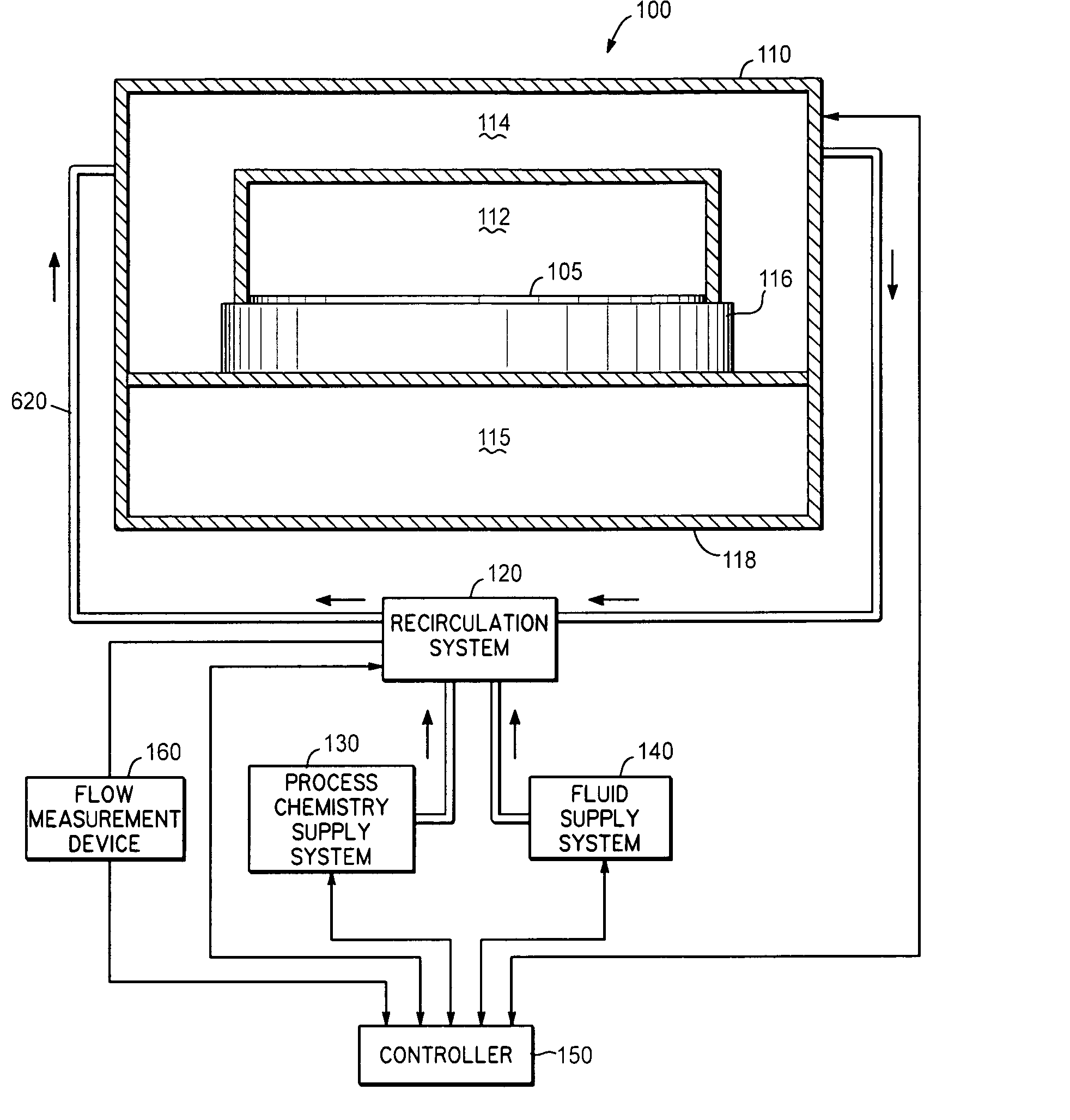
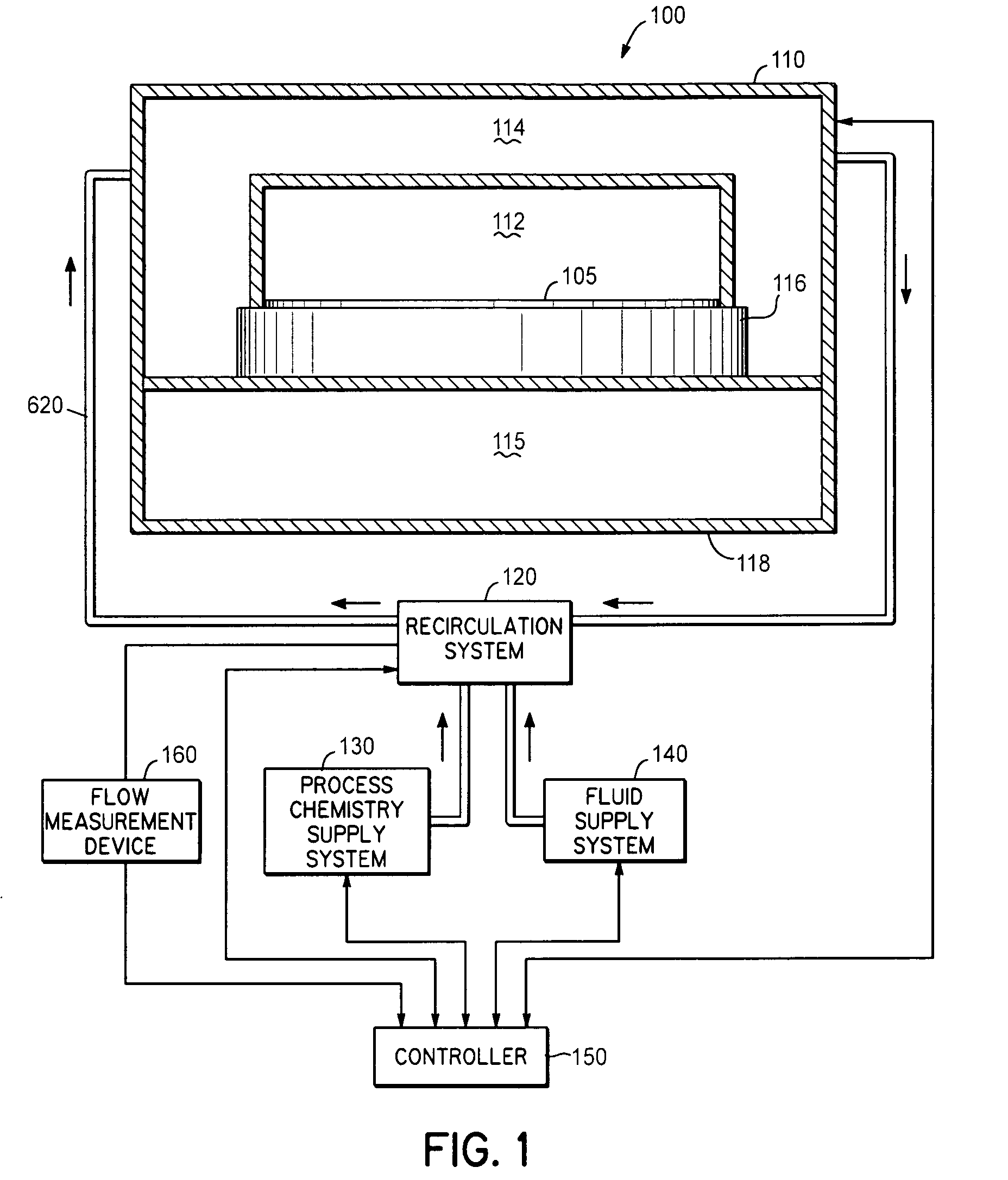
[0027] Referring now to the drawings, wherein like reference numerals designate identical or corresponding parts throughout the several views, FIG. 1 illustrates a processing system 100 according to an embodiment of the invention. In the illustrated embodiment, processing system 100 is configured to treat a substrate 105 with a high pressure fluid, such as a fluid in a supercritical state, and an additive, such as a process chemistry. The processing system 100 comprises processing elements that include a processing chamber 110, a fluid flow system 120, a process chemistry su...


PUM

PropertyMeasurementUnit
pressureaaaaaaaaaa
pressureaaaaaaaaaa
critical pressureaaaaaaaaaa

Abstract

In a high pressure processing system configured to treat a substrate, a flow measurement device is utilized to determine a flow condition in the high pressure processing system. The flow measurement device can, for example, comprise a turbidity meter. The flow parameter can, for example, include a volume flow rate or a time to achieve mixing of a process chemistry within a high pressure fluid used to treat the substrate.

Description

BACKGROUND OF THE INVENTION [0001] 1. Field of the Invention [0002] The present invention relates to a method and system for determining a flow condition in a high pressure processing system configured to treat a substrate and, more particularly, to a method and system for maintaining fluid flow in a high pressure processing system. [0003] 2. Description of Related Art [0004] During the fabrication of semiconductor devices for integrated circuits (ICs), a sequence of material processing steps, including both pattern etching and deposition processes, are performed, whereby material is removed from or added to a substrate surface, respectively. During, for instance, pattern etching, a pattern formed in a mask layer of radiation-sensitive material, such as photoresist, using for example photolithography, is transferred to an underlying thin material film using a combination of physical and chemical processes to facilitate the selective removal of the underlying material film relative t...

Claims


Application Information

Patent Timeline
Patent Type & Authority Applications(United States)
IPC IPC(8): B08B6/00G03C5/00C23C14/00
CPCG01N21/53H01L21/67017
Inventor PARENT, WAYNE M.
Owner TOKYO ELECTRON LTD
Why Eureka
Try Eureka