Al-Ni-rare earth element alloy sputtering target

Inactive Publication Date: 2006-08-17
KOBE STEEL LTD +1
View PDF17 Cites 38 Cited by
  • Summary
  • Abstract
  • Description
  • Claims
  • Application Information

AI Technical Summary

Benefits of technology

[0015] According to the target of the present invention, even when used as a large-size sputtering target, the target does not get deformed (warp) greatly even during rolling, bonding to a cooling plate and repeated use for film deposition.
[0016] This makes it possible to precisely produce a target of a specified size in an easy manner. This also attains easy bonding to a cooling plate and allows omission of straightenin

Problems solved by technology

Warp of the target which occurs during producing may be warp of a plate at the stage of mechanical processing due to the residual stress which remains after rolling or straightening, thermal deformation during bonding to a cooling plate, etc., and if such deformation is excessive, not only the accuracy of the product but the productivity as well deteriorate.
Meanwhile, th

Method used


Image

  • Al-Ni-rare earth element alloy sputtering target
  • Al-Ni-rare earth element alloy sputtering target
  • Al-Ni-rare earth element alloy sputtering target

Examples


example 1

[0046] N2 gas was blown against the Al alloy materials No. 1 through No. 10 and No. 14 through No. 16 having the compositions shown in Table 1 during spray forming under the conditions provided in Table 1, intermediate materials (whose densities were approximately from 50 to 60%) were consequently obtained and then encapsulated and degassed, and thereafter pressed using an HIP machine. These were forged into plate-shaped materials, rolled (at the total processing rate of 80%, the processing rate per pass of 6 through 10% and the finish rolling temperature of 400 degrees Celsius) so that the plate thickness would be approximately the same as that of the final products (targets), annealed (400 degrees Celsius) and then mechanically processed, thereby obtaining Al alloy plates of 8 mm t×600 mm×800 mm. Other conditions for spray forming than those appearing in Table 1 are as follows: [0047] Superheat: 200 degrees Celsius [0048] Over pressure: initial . . . 0.003 MPa end . . . 0.01 MPa

[...

example 2

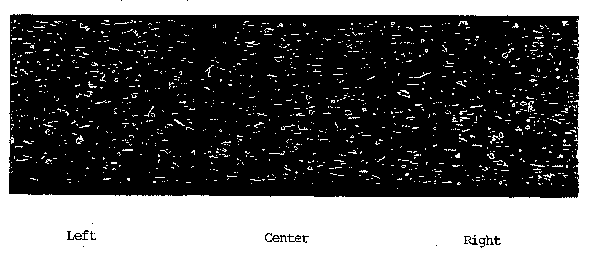
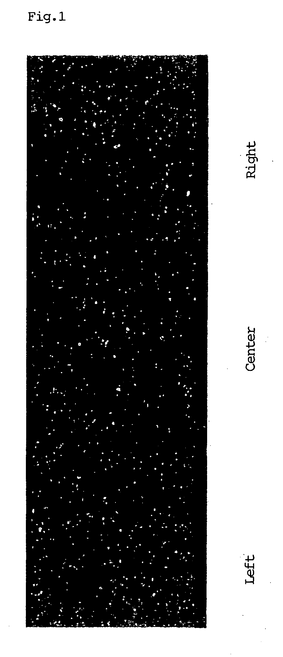
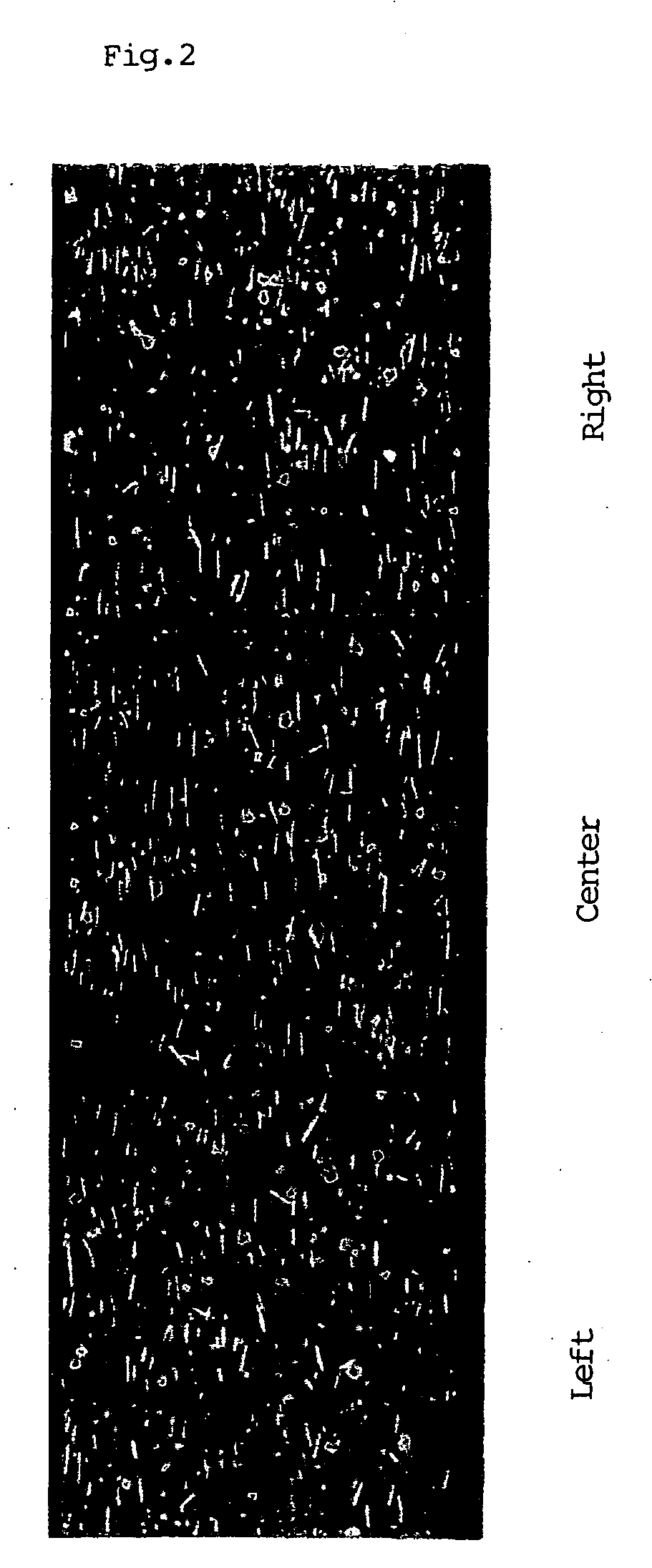
[0053] Al alloy materials obtained by spray forming under the recommended conditions were rolled under various conditions, and the structures of Al alloy plates and the influence over film deposition were examined. More specifically, after obtaining intermediate materials by spray forming under similar conditions to those used for No. 1 through No. 10 described in Example 1, the intermediate materials were encapsulated and degassed, and thereafter pressed using an HIP machine. These were forged into plate-shaped materials, rolled under the conditions shown in Table 2, annealed (400 degrees Celsius) and then mechanically processed, thereby obtaining Al alloy plates of 8 mm t×600 mm×800 mm.

[0054] As in Example 1, a cross sectional surface of each Al alloy plate thus obtained perpendicular to the plane of each Al alloy plate was observed with a microscope, and the number of compounds whose aspect ratio was 2.5 or higher and whose equivalent diameter was 0.2 μm or larger was counted. A...


PUM

PropertyMeasurementUnit
Fractionaaaaaaaaaa
Angleaaaaaaaaaa
Diameteraaaaaaaaaa

Abstract

An Al-base alloy sputtering target consisting Ni and one or more rare earth elements, wherein there are 5.0×10⁴/mm2 or more compounds whose aspect ratio is 2.5 or higher and whose equivalent diameter is 0.2 μm or larger, when a cross sectional surface perpendicular to the plane of the target is observed at a magnification of 2000 or higher.

Description

BACKGROUND OF THE INVENTION [0001] 1. Field of the Invention [0002] The present invention relates to an Al—Ni-rare earth element alloy sputtering target, and more particularly, to such an Al—Ni-rare earth element alloy sputtering target which can be produced favorably even when the target is to be made large and with which it is possible to realize stable sputtering which does not accompany major warp of the target. [0003] While the sputtering target according to the present invention is applicable to an interconnection film which forms a liquid crystal panel, an organic EL panel or the like for use in a television set, a laptop computer, a monitor or other display, a reflection film, a recording film and the like for use in the field of optical recording, an interconnection film and the like in the field of semiconductor devices, use of the sputtering target according to the present invention for a liquid crystal panel will be described below as a typical application. [0004] 2. Des...

Claims


Application Information

Patent Timeline
IPC IPC(8): C22C21/00
CPCB22F2003/248B22F2998/10B22F2999/00C22C1/0416C22C21/00C23C14/3414B22F9/082B22F3/1208B22F3/15B22F3/17B22F3/18B22F3/24B22F2201/02C23C14/0688
Inventor KUGIMIYA, TOSHIHIROTAKAGI, KATSUTOSHIMATSUZAKI, HITOSHIKITASHITA, KOTAROYONEDA, YOICHIRO
Owner KOBE STEEL LTD
Why Eureka
Try Eureka