Electric motor unit with controller

Inactive Publication Date: 2006-08-17
HITACHI LTD +1
View PDF6 Cites 19 Cited by
  • Summary
  • Abstract
  • Description
  • Claims
  • Application Information

AI Technical Summary

Benefits of technology

[0032] Further, according to the electric motor unit with a controller of the present invention, in an electric motor unit with a controller for switching the operation condition of the dri

Problems solved by technology

In the conventional electric motor unit with a controller as mentioned above, the printed wiring board for control mounting the microcontroller is incorporated in the housing assembly having the built-in gear train, so that the printed wiring board is exposed in a very bad atmosphere in which oil of the housing assembly and worn metallic powder of the gears are floating, and the magnetic field for the non-contact sensor is disturbed, and there is a fear of a malfunction.
Further, the housing assembly becomes warm due to heat of the motor and frictional heat by rotation of the gear train, so that the printed wiring board in the housing assembly is exposed in a high-temperature atmosphere and there is a fear of a thermal malfunction.
Therefore, it is difficult to detect stably an accurate rotational position.
The wiring board for controlling to drive the electric motor includes a large current wiring pattern of the motor drive system, a signal pattern, and a sensor pattern and the prior art arranges a large current wiring pattern at the same potential extending over a plurality of condu

Method used


Image

  • Electric motor unit with controller
  • Electric motor unit with controller
  • Electric motor unit with controller

Examples


Embodiment Construction

[0051] Hereinafter, the embodiments of the present invention will be explained in detail with reference to the accompanying drawings.

[0052] Power transfer system of a four-wheel drive car:

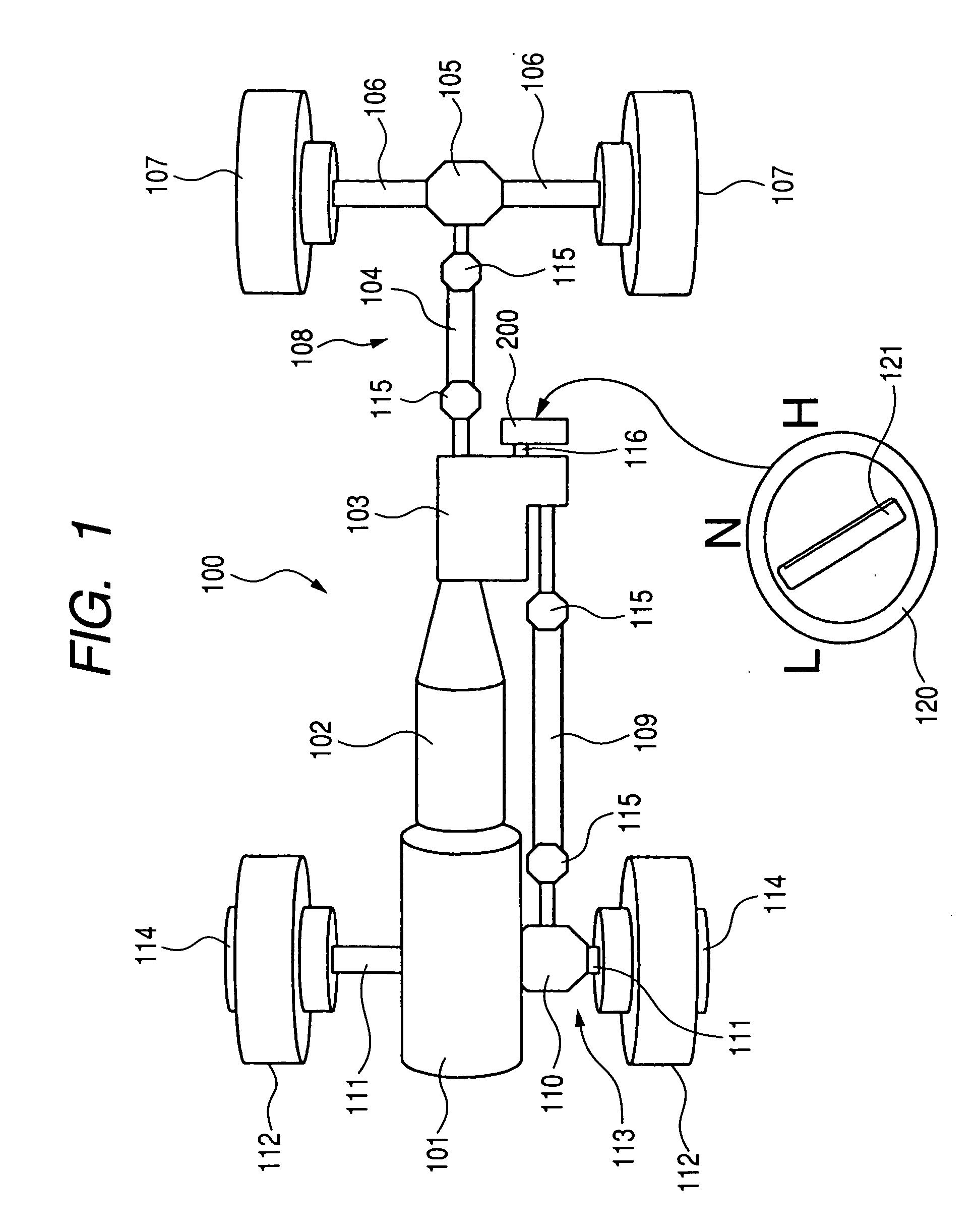
[0053]FIG. 1 shows the power transfer system of a car of a four-wheel drive type to which the electric motor unit with a controller of the present invention is applied.

[0054] The drive train of the four-wheel drive car is schematically shown with a reference number of 100. The drive train 100 of the four-wheel drive car is connected to a motor 101 such an internal combustion engine and has a transmission 102 driven by the motor 101. The transmission 102 may be either of the general automatic type and manual type.

[0055] To the latter stage of the transmission 102, a transfer case assembly 103 for four-wheel drive switching is connected. The transfer case assembly 103 always supplies driving force to a rear wheel drive line 108 including a back thrust shaft 104, a back differential device 105, a ...


PUM


Abstract

An object of the present invention is to provide an electric motor unit with a controller of a machinery and electricity integration type for eliminating variations due to mechanical factors and obtaining excellent operation reliability. A magnet member is attached to a gear on the side of a gear case, and a sensor for sensing the magnet member and detecting a rotational angle of the gear in a controller case, and a cylindrical opening concentric with the rotational center of the gear is installed on the gear case, and a cylindrical part fitting into the cylindrical opening is installed on the controller case, and the controller case is positioned and mounted on the gear case by the fitting between the cylindrical part and the cylindrical opening.

Description

CLAIM OF PRIORITY [0001] The present application claims priority from PCT application No. PCT / JP03 / 00717, filed on Jan. 27, 2003, the content of which is hereby incorporated by reference into this application.FIELD OF THE INVENTION [0002] The present invention relates to an electric motor unit with a controller and more particularly to an electric motor unit with a controller of a machinery and electricity integration type used in components of the drive system of a car such as a transmission and four-wheel drive transfer. BACKGROUND OF THE INVENTION [0003] As an electric motor unit with a controller for switching the operation condition of the drive line of a car such as a transmission and four-wheel drive transfer, there is a machinery and electricity integration type (for example, U.S. Pat. No. 6,155,126) available which has a built-in gear train of deceleration system for driving to rotate a switching operation member such as a shift rail of four-wheel drive transfer in one hous...

Claims


Application Information

Patent Timeline
IPC IPC(8): H02K11/00H02K7/10H02K23/66
CPCF16H61/0003F16H61/32F16H2063/005H02K11/0084H02K7/1166H02K11/38
Inventor SAITO, MASASHINAKANO, YOUICHIKAMESHIRO, YASUROTAZAWA, SATOSHIHARADA, KOUJI
Owner HITACHI LTD
Why Eureka
Try Eureka