Information recording and reproducing apparatus and method, and signal decoding circuit for performing timing recovery

a signal decoding circuit and information recording and reproducing technology, applied in the direction of digital signal error detection/correction, instruments, line-transmission details, etc., can solve the problems of deteriorating format efficiency of magnetic recording and reproducing apparatus, difficult to obtain no consideration of frequency offset, etc., to achieve a wide frequency lead-in range, high density recording, and shorten the length of the preamble

Inactive Publication Date: 2006-08-17
TOSHIBA STORAGE DEVICE CORP
View PDF8 Cites 90 Cited by
  • Summary
  • Abstract
  • Description
  • Claims
  • Application Information

AI Technical Summary

Benefits of technology

[0010] According to the invention, there are provided information recording and reproducing apparatus and method and a signal decoding circuit, in which a length of preamble is shortened, a frequency lead-in range is widened, a high density recording can be performed, and reliability can be raised. (Information Recording and Reproducing Apparatus-1)

Problems solved by technology

However, no consideration is given to a frequency offset, and it is difficult to obtain a wide frequency lead-in range.
There is a problem such that format efficiency of the magnetic recording and reproducing apparatus deteriorates.

Method used


Image

  • Information recording and reproducing apparatus and method, and signal decoding circuit for performing timing recovery
  • Information recording and reproducing apparatus and method, and signal decoding circuit for performing timing recovery
  • Information recording and reproducing apparatus and method, and signal decoding circuit for performing timing recovery

Examples


embodiment

Fundamental Embodiment

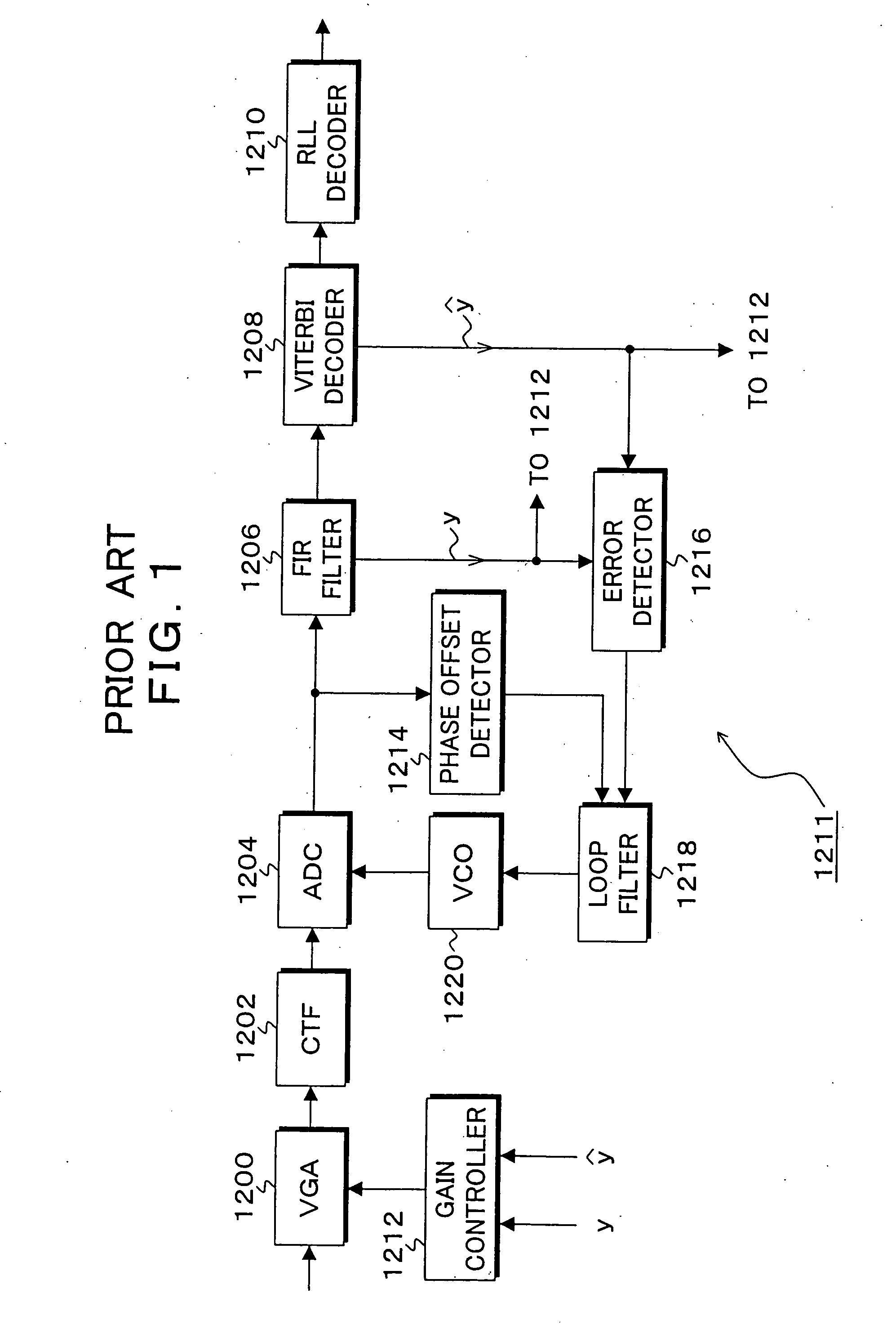
[0097]FIG. 4 is a block diagram of a hard disk drive to which the invention is applied. The hard disk drive is constructed by an SCSI controller 10, a drive control 12, and a disk enclosure 14. Naturally, an interface with a host is not limited to the SCSI controller 10 but other proper interface controller can be used. The SCSI controller 10 is provided with: an MCU (Main Control Unit) 16; a memory 18 using a DRAM or an SRAM which is used as a control storage; a program memory 20 using a non-volatile memory such as a flash memory or the like for storing a control program; a hard disk controller (HDC) 22; and a data buffer 24. A drive interface logic 26, a DSP 28, a read channel (RDC) 30, and a servo driver 32 are provided for the drive control 12. A head IC 34 is further provided for the disk enclosure 14. Combination heads 36-1 to 36-6 each having a recording head and a reproducing head are connected to the head IC 34, respectively. The combination heads 36-1...


PUM

PropertyMeasurementUnit
phaseaaaaaaaaaa
phase erroraaaaaaaaaa
phase offset detectoraaaaaaaaaa

Abstract

A timing recovery unit detects a phase offset and a frequency offset from a head area of reproduction data and initially corrects them. The timing recovery unit stores data in which a head reproduction signal has been made to be discrete by a fixed clock into a buffer. A phase offset detector detects the phase offset from the data head area in parallel with the operation for writing the data into the buffer. At the same time, a frequency offset detector detects the frequency offset from the data head area in parallel with the operation for writing the data into the buffer. A correction value of the detected phase offset and a correction value of the detected frequency offset are initially set into a digital PLL. While the data is read out from the buffer, a frequency lead-in and a phase lead-in are executed in the head area.

Description

[0001] This is a Divisional of application Ser. No. 10 / 273,485 filed Oct. 18, 2002.BACKGROUND OF THE INVENTION [0002] 1. Field of the Invention [0003] The invention relates to an information recording and reproducing apparatus of a magnetic disk, an MO, an optical disk, a magnetic tape, or the like, an information recording and reproducing method, and a signal decoding circuit. More particularly, the invention relates to information recording and reproducing apparatus and method and a signal decoding circuit, for performing a timing recovery after a head reproduction signal is made discrete by an asynchronous clock. [0004] 2. Description of the Related Arts [0005] In a conventional timing reproduction loop for a timing recovery of a read channel LSI, a sampling clock in an A / D converter and a symbol rate clock for making discrimination are the same. To obtain optimum discrimination timing, therefore, it is necessary for directly controlling a phase of the sampling clock of the A / D c...

Claims


Application Information

Patent Timeline
Patent Type & Authority Applications(United States)
IPC IPC(8): G11B5/09G11B5/035G11B7/005G11B20/14G11B20/10G11B20/18H04B3/06
CPCG11B5/09G11B20/10009G11B20/18
Inventor SUGAWARA, TAKAOTAKATSU, MOTOMUSAWADA, MASARU
Owner TOSHIBA STORAGE DEVICE CORP
Why Eureka
Try Eureka