
Oriented sheath core type filament

a technology of super microfilaments and sheath cores, which is applied in the direction of manufacturing tools, electric/magnetic/electromagnetic heating, transportation and packaging, etc., can solve the problems of high cost, inability to produce at stable operation, and inability to meet the production methods of high-performance fibers, so as to achieve easy production of super microfilaments, high speed, and simple and convenient means

Inactive Publication Date: 2006-08-17
YAMANASHI UNIV OF
View PDF4 Cites 20 Cited by
  • Summary
  • Abstract
  • Description
  • Claims
  • Application Information

AI Technical Summary

Benefits of technology

[0006] This invention is further developed on the above conventional technology and the object is to obtain easily sheath-core type super microfilaments by simple and convenient method without the need of special, high-accuracy and high-level apparatus. And the other object is to enable stable manufacturing of sheath-core type filaments such as hollow filaments, optical filaments and conjugate filaments in high quality and fine diameters of filaments. Moreover, the other object is to provide sheath-core type filaments in which a drawn portion of the drawn hollow super microfilaments, drawn optical super microfilament and the like and un-drawn original filaments are connected in a unified manner. Further, the other object is to enable the manufacturing of long fiber non-woven fabrics consisting of sheath-core type filaments such as hollow supper microfilaments and conjugate super microfilaments. Means to Solve the Problems

Problems solved by technology

However, since special and complicated spinning methods such as island-in-sea type fiber spinning (for example, Japanese Patent Laid-Open No.
Hei 7-258940) or spinning by dividual fibers (for example, Japanese Patent Laid-Open 2002-220740) have been used, for the production of highly molecular oriented super microfilaments and having high quality with the fiber diameter of 5 μm or less, they are expensive and cannot be drawn simply and conveniently by using general purpose fibers.
However, it is difficult to produce at stable operation as the apparatus is more complicated and precise so that is expensive by the conventional method to obtain super micro fibers.
And the manufacturing methods of the conventional super micro fibers are not match the production of high performance fibers as their production is high-mix low-volume production that it has been required the manufacturing means of high performance fibers of high quality in more simple and convenient ways.

Method used

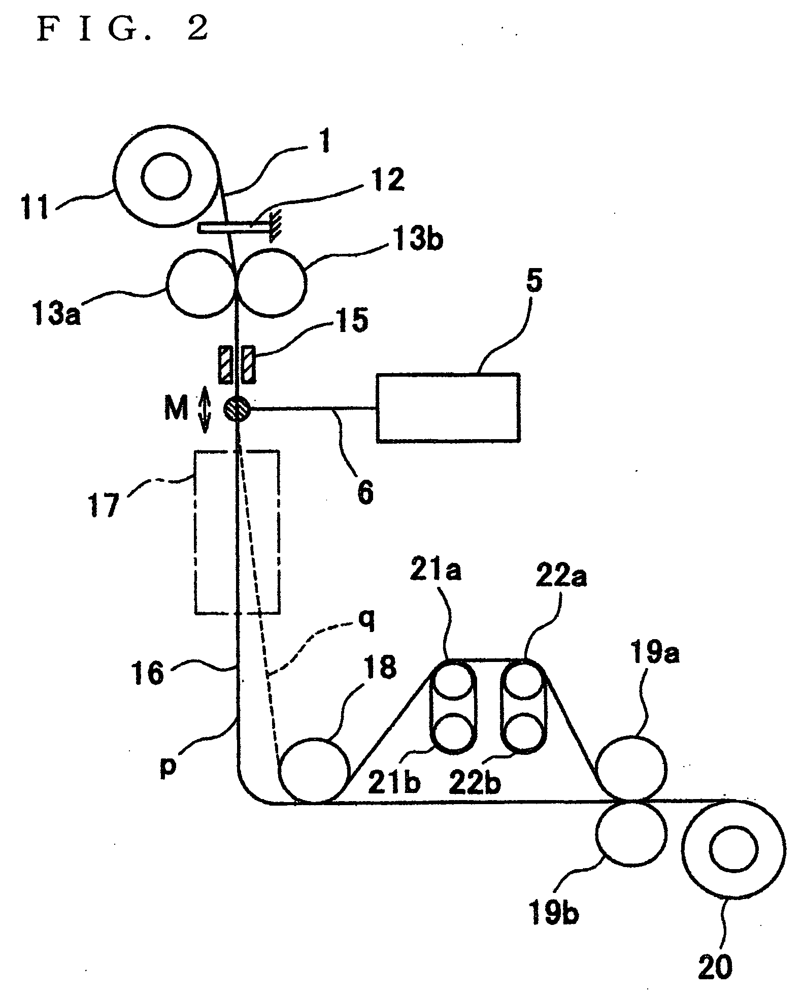
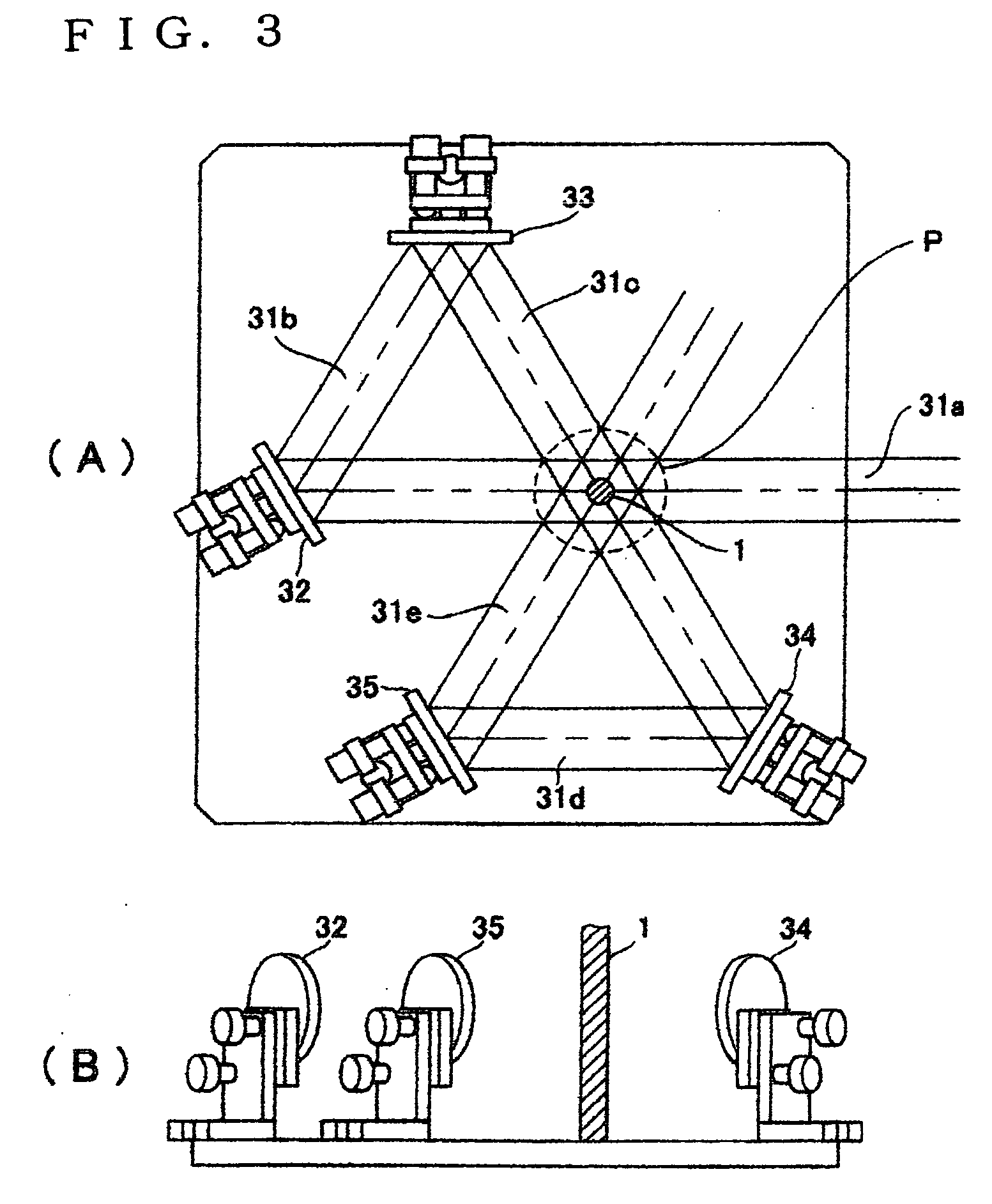

Image

  • Oriented sheath core type filament
  • Oriented sheath core type filament
  • Oriented sheath core type filament

Examples


example 1

[0067] Isotactic (it) polypropylene hollow filaments (filament diameter 280 μm, inside diameter 90 μm) were used as the original sheath-core type filaments. These filaments were drawn by the drawing apparatus shown in FIGS. 2 and 3. The experimental results for the filament diameter (outside diameter) and the inside diameter of obtained filaments by changing the supplying speed of the original filaments variously and also the wind-up speed were shown in FIG. 8. In this case, a carbon dioxide gas laser emitter manufacture by Onizuka Glass Co., Ltd. with a maximum power of 10 W was used for the laser emitter. The laser power density was 28.5 W / cm2 (1.2 W) at a supplying speed of 0.3 m / min and as the supplying speed was increased the power density was increased, and was 52.5 W / cm2 (2.2 W) at 0.6 m / min. The laser beam diameter in this case was 4.0 mm. The drawn sheath-core type filaments run along the trace “p” in FIG. 2 and the distance from the laser heating portion M to lowermost pos...

example 2

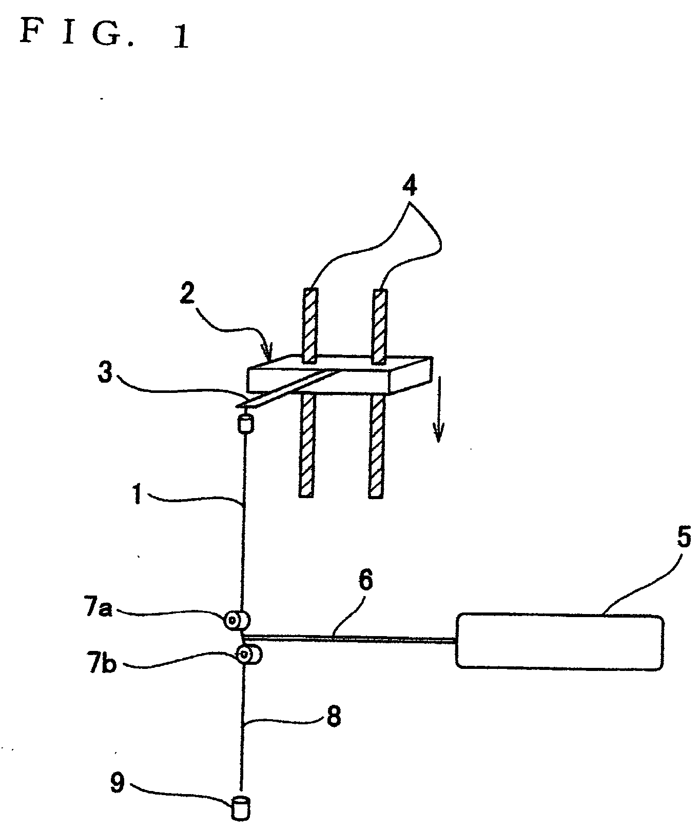
[0068] Poly(methyl methacrylate) series optical filaments (filament diameter 250 μm) as the original sheath-core type filaments were drawn at a supplying speed of 0.3 m / min by the similar means to Example 1. It was conducted with a power density of 23.9 W / cm2. In this case, the drawn filaments with a filament diameter of 14 μm (draw ratio 319 times) at a winding speed of 139.8 m / min, the filament diameter of 12 μm (draw ratio 433 times) at a winding speed of 226.2 m / min and the filament diameter of 7 μm (draw ratio 1274 times) at a winding speed of 400 m / min were obtained. When the drawing tension corresponds to each of these drawing ratios were measured by the load cell according to the method shown in FIG. 1, they were 0.12 MPa at a filament diameter of 14 μm, 0.18 MPa at the filament diameter of 12 μm and 0.25 MPa at a filament diameter of 7 μm. Still, drawing of the high drawing ratio of 100 times or more was not possible under the tension of more than 10 MPa. Also, the drawing ...


PUM

PropertyMeasurementUnit
diametersaaaaaaaaaa
diametersaaaaaaaaaa
light transmittanceaaaaaaaaaa

Abstract

The object of this invention is to make possible the manufacturing of sheath-core type super microfilaments from sheath-core type filaments such as hollow filaments, optical filaments and conjugate filaments continuously and stably by a simple and convenient means without requiring any apparatus of high-accuracy and high-level, characterized in that original filaments delivered from sheath-core type filament supply means are heated by infrared beams and the heated sheath-core type filaments are drawn at 100 times or more by a tension provided by the own weight or under a tension of 1 MPa or less.

Description

1. FIELD OF THE INVENTION [0001] This invention concerns a method of and an apparatus for manufacturing drawn sheath-core type filaments and it especially relates to sheath-core type super microfilaments such as hollow super microfilaments, optical super microfilaments, conjugate super microfilaments drawn at a high draw ratio of 100 times or more and obtained by the simple and convenient drawing method. 2. BACKGROUND OF THE INVENTION [0002] Super microfilaments have been used in various applications such as artificial leathers, wiping cloths and filters. However, since special and complicated spinning methods such as island-in-sea type fiber spinning (for example, Japanese Patent Laid-Open No. Hei 7-258940) or spinning by dividual fibers (for example, Japanese Patent Laid-Open 2002-220740) have been used, for the production of highly molecular oriented super microfilaments and having high quality with the fiber diameter of 5 μm or less, they are expensive and cannot be drawn simply...

Claims


Application Information

Patent Timeline
Patent Type & Authority Applications(United States)
IPC IPC(8): D02G3/00D02J1/22D04H1/4382D04H3/02
CPCD02J1/22Y10T428/2913D04H3/02D02J1/224
Inventor SUZUKI, AKIHIRO
Owner YAMANASHI UNIV OF
Learn More