Trans-septal catheter with retention mechanism

Inactive Publication Date: 2006-08-17
STEWART MARK T +2
View PDF4 Cites 139 Cited by
  • Summary
  • Abstract
  • Description
  • Claims
  • Application Information

AI Technical Summary

Benefits of technology

[0013] The present invention is directed to an improved trans-septal guide catheter that can be passed through a septum from one heart chamber to another heart chamber and that possesses a retention mechanism for maintaining a distal segment thereof in the other heart chamber. For example, the trans-se

Problems solved by technology

While drugs may be the treatment of choice for many patients, drugs typically only mask the symptoms and do not cure the underlying cause.
Implantable electrical stimulators, e.g., pacemakers, afferent nerve stimulators and cardioverter/defibrillators, which have proven to provide successful treatment, usually can only correct an arrhythmia after it o

Method used


Image

  • Trans-septal catheter with retention mechanism
  • Trans-septal catheter with retention mechanism
  • Trans-septal catheter with retention mechanism

Examples


first embodiment

[0048]FIG. 3 is a simplified schematic illustration of a guide catheter 70 of the present invention having a deployable retention mechanism comprising an expandable balloon 78 expanded in the LA and drawn against the septal wall in the LA of the septum 66 to inhibit retraction of the guide catheter distal segment 76 into the RA. FIG. 4 is a cross-section view along lines 4-4 of FIG. 3 depicting the guide catheter lumen 72 and balloon inflation / deflation lumen 82 within the guide catheter body 80.

[0049] The inflatable balloon 78 is inflated and deflated through the inflation / deflation lumen 82 that extends within the guide catheter body 80 from a proximal inflation port 86 at the guide catheter proximal end 74 to a balloon inflation port 84 within the inflatable balloon 78. The inflation medium (preferably a fluid, e.g., saline or a radiopaque solution) is introduced through the balloon inflation / deflation lumen 82 to inflate the balloon 78 after the deflated balloon 78 is advanced t...

second embodiment

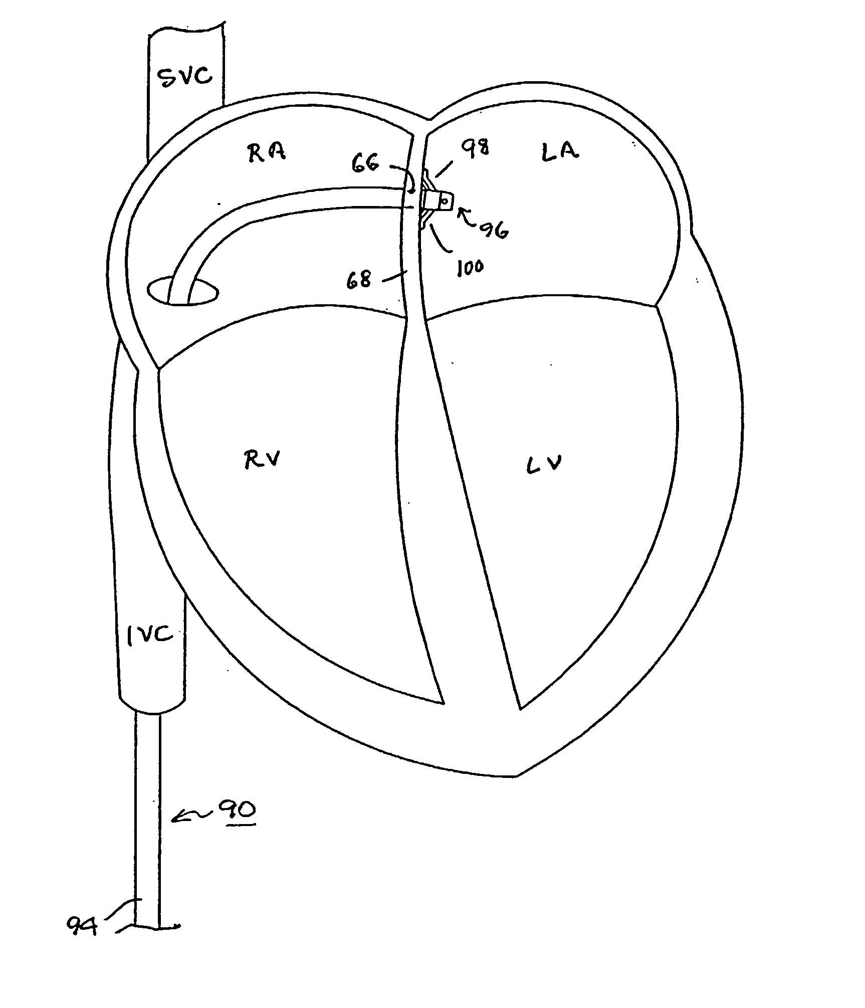
[0051]FIG. 5 illustrates a guide catheter 90 of the present invention having a self deployed retention mechanism that includes a plurality of pliant tines 98,100 drawn against the septum in the LA to inhibit retraction of the guide catheter distal segment 96 through the perforation 66 into the RA. FIG. 6 is an end view of the distal segment 96 of the guide catheter of FIG. 5 depicting the guide catheter lumen 92 and outwardly extending tines 98 and 100.

[0052] Each such flexible, pliant, tine 98,100 extends outwardly from a tine attachment 102,104 with the distal segment of the guide catheter body to a respective tine free end 106,108. Preferably, the flexible, pliant, tines 98, 100 extend proximally and outwardly from the respective tine attachments 102,104 with the guide catheter body 94 at an acute angle to the guide catheter body 94. The tines 98,100 can be rectangular or circular in cross-section and can be thinner or thicker than depicted and longer or shorter than depicted. Th...

third embodiment

[0055]FIG. 7 illustrates a guide catheter 110 of the present invention having a deployable retention mechanism that includes an extendable wire 112 that forms a wire coil 114 when extended from a wire deployment lumen 118 (shown in FIG. 12) into the LA and inhibits retraction of the guide catheter distal segment 116 into the RA. The catheter body 122 encloses a guide catheter lumen 124 (FIG. 12) adapted to receive a mapping / ablation EP catheter and the wire deployment lumen 118 extending between a deployment lumen proximal end opening and a deployment lumen distal end opening in the distal segment 120. FIG. 8 shows the extendable wire 112 that forms a wire coil 114 when extended into the LA retracted into the wire lumen 118 during introduction into or withdrawal from the RA of the distal segment 116 through the perforation 66 in the septum 68.

[0056] In use, the elongated retention wire 112 is extended at guide catheter proximal end 126 through the wire deployment lumen 118 to dispos...


PUM


Abstract

A trans-septal guide catheter for providing access through the septum separating a first heart chamber from a second heart chamber that includes an elongated guide catheter body extending between guide catheter proximal and distal ends. A distal segment of the guide catheter is adapted to be inserted through the septum to locate the distal segment of the guide catheter within one of the first heart chamber and the second heart chamber. The catheter body encloses a guide catheter lumen adapted to provide access into the one of the first heart chamber and the second heart chamber through a guide catheter lumen proximal end opening and a guide catheter lumen distal end opening. A retention mechanism engages the septum and maintains the distal segment of the guide catheter extending into the one of the first heart chamber and the second heart chamber

Description

REFERENCE TO PRIORITY APPLICATION [0001] This application claims the benefit of U.S. Provisional Application No. 60 / 292,483, FILED May 21, 2001, entitled “TRANS-SEPTAL GUIDE CATHETER WITH RETENTION MECHANISM”, incorporated herein by reference in its entirety.FIELD OF THE INVENTION [0002] The present invention relates generally to trans-septal introducers or guide catheters adapted to introduce an instrument through the septum between a left and right heart chamber, and more particularly, the present invention relates to a trans-septal guide catheter having a retention mechanism for retaining the distal end of the guide catheter within the left heart chamber particularly to enable passage therethrough of an electrophysiology (EP) catheter. BACKGROUND OF THE INVENTION [0003] The heart includes a number of pathways through which electrical signals necessary for normal, electrical and mechanical synchronous function of the upper and lower heart chambers propagate. Tachycardia, that is a...

Claims


Application Information

Patent Timeline
IPC IPC(8): A61N1/05A61B17/00A61F2/958
CPCA61B17/00234A61B2017/00252A61M25/10
Inventor STEWART, MARK T.FRANCISCHELLI, DAVID E.SKARDA, JAMES R.
Owner STEWART MARK T
Why Eureka
Try Eureka