Laser beam machine

a laser beam machine and laser beam technology, applied in the field of laser beam machines, can solve the problems of complex construction of the welding apparatus and inability to obtain high working efficiency, and achieve the effects of improving production yield, shortening processing time, and improving working efficiency

Inactive Publication Date: 2006-08-24
HAMAMATSU PHOTONICS KK
View PDF4 Cites 7 Cited by
  • Summary
  • Abstract
  • Description
  • Claims
  • Application Information

AI Technical Summary

Benefits of technology

[0008] In this laser beam machine, while the pressing portion of the optical guide member presses the first workpiece material against the second workpiece material, a laser beam propagated through the optical fiber is annularly guided by the optical guide member and outputted from the pressing portion. Thereby, the entire annular processing region of the first and second workpiece materials is irradiated with the laser beam at one time, whereby the first workpiece material can be joined to the second workpiece material. This improves the working efficiency. Such improvement in working efficiency shortens the processing time and improves the production yield. Furthermore, this laser beam machine does not need to be separately provided with a rotating mechanism for laser beam scanning and a pressurizing mechanism for the first and second workpiece materials, so that construction of the machine can be significantly simplified.
[0009] It is preferable that a groove having a bottom from which the laser beam exits is annularly formed in the pressing portion. Thereby, the pressing portion can be separated from the processing region, so that the first workpiece material can be prevented from being welded to the optical guide member when it is joined. Thereby, the working efficiency for joining can be further improved.
[0010] It is preferable that the optical guide member is formed into a cap shape broaden toward the pressing portion from the connecting portion. With such a construction of the optical guide member, it can be easily and reliably realized that the first workpiece material is pressed against the second workpiece material and that a laser beam introduced from the optical fiber is annularly guided toward the pressing portion.

Problems solved by technology

However, in the conventional welding method, it is necessary to scan a laser beam along the overlapping portion between the first and second workpiece materials, so that high working efficiency cannot be obtained.
In addition, a pressuring mechanism for the first and second workpiece materials and a rotating mechanism for scanning a laser beam are necessary, so that construction of the welding apparatus becomes complicated.

Method used


Image

  • Laser beam machine
  • Laser beam machine
  • Laser beam machine

Examples


Embodiment Construction

[0017] A preferred embodiment of the laser beam machine according to the invention is explained in detail with reference to the drawings.

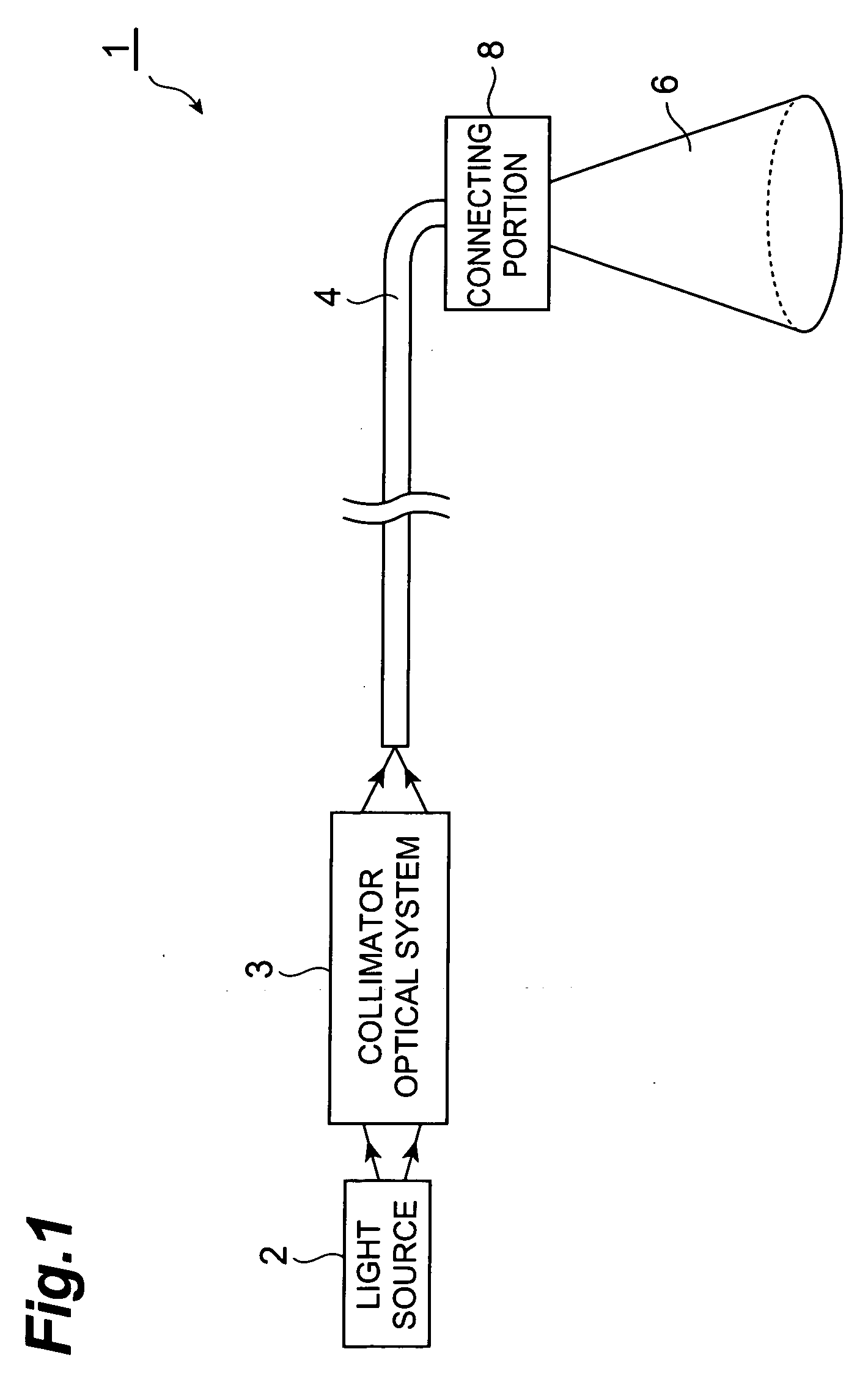
[0018]FIG. 1 is a construction view of an embodiment of a laser beam machine constructed according to the invention. The laser beam machine 1 shown in FIG. 1 is constructed for joining a lid to a body of a container at a canning site. This laser beam machine 1 comprises a light source 2 that outputs a laser beam, a collimator optical system 3 that shapes the laser beam outputted from the light source 2, an optical fiber 4 that propagates the laser beam shaped by the collimator optical system 3, and an optical guide member 6 that outputs the laser beam propagated through the optical fiber 4 to a processing region.

[0019] As the light source 2, for example, a semiconductor laser array is used. A laser beam outputted at a predetermined power from this light source 2 is collimated and condensed by the collimator optical system 3, and coupled to the co...


PUM

PropertyMeasurementUnit
diameteraaaaaaaaaa
heightaaaaaaaaaa
poweraaaaaaaaaa

Abstract

In this laser beam machine 1, while a pressing portion 9 of an optical guide member 6 presses a lid 13 against a body 12 of a container, the optical guide member 6 annularly guides a laser beam propagated through an optical fiber 4 and outputs it from the pressing portion 9. Thereby, an annular processing region of the body 12 and the lid 13 is entirely irradiated with the laser beam at one time and the lid 13 can be joined to the body 12, whereby improving the working efficiency. Such improvement in working efficiency shortens the processing time and improves the production yield. Furthermore, this laser beam machine 1 does not need to be separately provided with a rotating mechanism for laser beam scanning and a pressurizing mechanism for the body 12 and the lid 13, so that construction of the machine can be significantly simplified.

Description

BACKGROUND OF THE INVENTION [0001] 1. Field of the Invention [0002] The present invention relates to a laser beam machine for joining a first workpiece material to a second workpiece material by irradiating a laser beam. [0003] 2. Related Background of the Invention [0004] Conventionally, as a technique related to this kind of field, for example, a laser beam welding method is described in Japanese Published Unexamined Patent Application No. H06-106371. In this welding method, while pressurizing with a pressurizing roll, first and second workpiece materials (for example, a body and a lid in canning) overlapped with each other are rotated and welded by scanning a laser beam along the overlapping portion. SUMMARY OF THE INVENTION [0005] However, in the conventional welding method, it is necessary to scan a laser beam along the overlapping portion between the first and second workpiece materials, so that high working efficiency cannot be obtained. In addition, a pressuring mechanism fo...

Claims


Application Information

Patent Timeline
Patent Type & Authority Applications(United States)
IPC IPC(8): B23K26/16
CPCB23K26/023B23K26/0734B23K26/246B23K26/28B29C65/1664B29C65/1687B29C66/545B29C66/542B29C66/21B29C65/1629B29C65/1667B29C65/1677B29C66/1312B23K26/037B23K26/244B29C66/71B29C66/24221B29K2067/003
Inventor KAN, HIROFUMIGONDA, SYUNICHIMIYAJIMA, HIROFUMIZHENG, YUJIN
Owner HAMAMATSU PHOTONICS KK
Why Eureka
Try Eureka