
Actuator, light quantity adjusting apparatus, and stepping motor

a technology of light quantity adjusting apparatus and stepping motor, which is applied in the direction of horology, instruments, magnetic circuit shape/form/construction, etc., can solve the problems of extreme slimming, difficult to locate a guide rod for a lens, and a great amount of space for coils and stators, etc., to achieve high efficiency, low cost, and high part fit

Inactive Publication Date: 2006-08-24
CANON KK
View PDF22 Cites 12 Cited by
  • Summary
  • Abstract
  • Description
  • Claims
  • Application Information

AI Technical Summary

Benefits of technology

[0026] A first object of the present invention is to provide an actuator which maintains high efficiency, can react to an increase in pole, has a high part fit, and can be manufactured at low cost while it is thinned, and a light quantity adjusting apparatus using the actuator as a driving source.
[0027] A second object of the present invention is to provide a high performance stepping motor which can react to an increase in pole, has a high part fit, and can be manufactured at low cost while it is thinned.

Problems solved by technology

In the conventional shutter apparatus, a coil and stators take up a great deal of base plate space.
Therefore, it is hard to locate another actuator, a guide rod for a lens, and the like.
Therefore, extreme slimming is difficult because efficiency of the actuator is likely to reduce owing to a reduction in magnetization efficiency of the magnet in the peripheral direction.
Therefore, a length of the stepping motor in the axial direction lengthens, so that it is hard to thin the stepping motor.
Therefore, when the number of magnetic poles of the stepping motor is intended to increase, a width of each of magnetic pole teeth and a gap between adjacent magnetic pole teeth become narrower, so that the difficulty in part processing increases and a physical strength reduces.
Therefore, a length of the stepping motor in the axial direction lengthens, so that it is hard to thin the stepping motor and a cost of parts increases.
In addition, the number of air gaps between the stators and magnets, by which a magnetic characteristic is significantly influenced, is four, so that the parts cannot be easily assembled with high precision.
It is necessary to pass the central rotating shaft through a large number of parts in order during assembly, so that an assembly time lengthens and it is likely to increase an assembly cost.
The number of parts is large, so that it is likely to reduce assembly precision due to the accumulation of part processing precision.
Thus, it is hard to construct a high performance stepping motor.
However, there are the following problems in the structural example.
Second, the coils are close to the stators in only upper and lower ends, so that the amount of leakage magnetic flux from the coils to the circumference is large.
Therefore, when the driving force is converted into torque, an unnecessary force in a transverse direction is likely to cause, with the result that there are concerns with respect to vibration, noise, non-uniform rotation, and a reduction in positional precision in the stepping motor.
The number of parts is large, thereby increasing a cost.
It is hard to achieve slimming.
High efficiency is hardly obtained.
It is hard to deal with an increase in number of poles.
Parts cannot be easily fit.

Method used


Image

  • Actuator, light quantity adjusting apparatus, and stepping motor
  • Actuator, light quantity adjusting apparatus, and stepping motor
  • Actuator, light quantity adjusting apparatus, and stepping motor

Examples


first embodiment

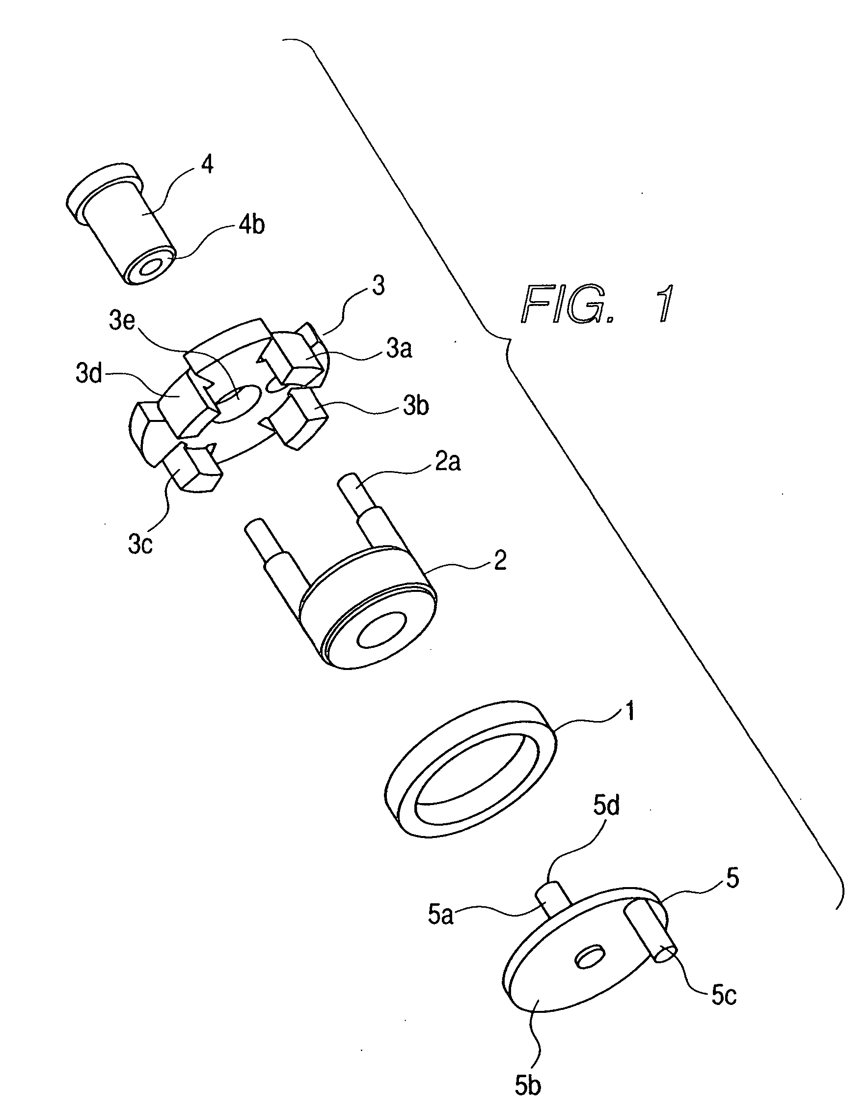
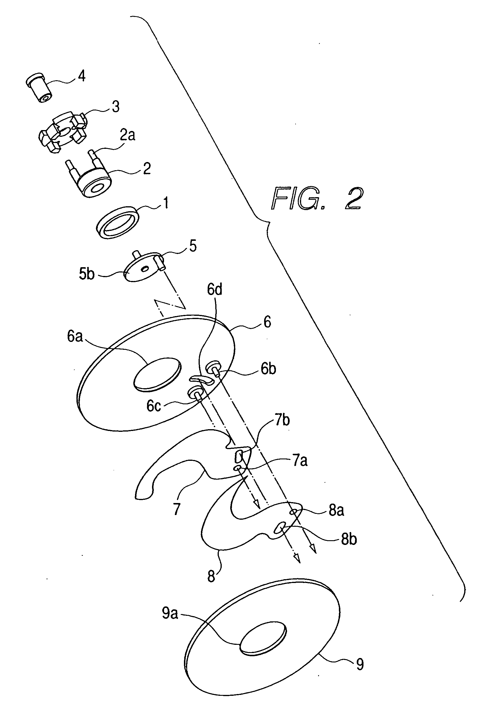
[0073] FIGS. 1 to 4 show an actuator and a light quantity adjusting apparatus according to a first embodiment of the present invention. More specifically, FIG. 1 is an exploded perspective view showing the actuator. FIG. 2 is an exploded perspective view showing a light quantity adjusting apparatus in which the actuator shown in FIG. 1 is incorporated as a driving source. FIG. 3 is a sectional view in an axial direction, showing the light quantity adjusting apparatus. FIGS. 4A and 4B are bottom views of B-B in FIG. 3, showing a state of rotation operation of a magnet. FIG. 4A shows a magnet and a stator in a state in which the magnet is rotated counterclockwise when viewed from a base plate side. FIG. 4B shows the magnet and the stator in a state in which the magnet is rotated clockwise by 30 degrees from the state shown in FIG. 4A by switching energization to the coil.

[0074] In FIGS. 1 to 4A and 4B, a ring magnet 1 has magnetized portions which are formed by dividing a surface of ...

second embodiment

[0106]FIG. 5 is a perspective view showing an actuator according to a second embodiment of the present invention. Only a point different from the first embodiment will be described.

[0107] In the first embodiment, each of the stator 3 and the bearing 4 is made of the soft magnetic material. In the second embodiment of the present invention, the stator 3 and the bearing 4 are integrally formed, so that a stator 13 having a bearing portion 13e is obtained. Such a structure can be realized by, for example, forging, drawing, or a metal injection mold manufacturing method.

[0108] In FIG. 5, the stator 13 includes not only magnetic pole teeth 13a, 13b, 13c, and 13d but also the bearing portion 13e and acts to smoothly rotate the stator 5. Therefore, a process for assembling the bearing and the stator in the first embodiment is unnecessary, so that a cost can be further reduced. When the two parts are separated from each other, four parts, that is, the magnet, the rotor, the bearing, and t...

third embodiment

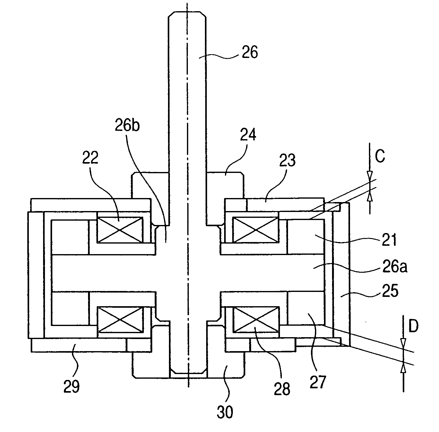
[0110]FIG. 6 is a sectional view in an axial direction, showing an actuator according to a third embodiment of the present invention, in which a stainless steel rod different from that in the first embodiment and the second embodiment is used as a shaft of a rotor.

[0111] In the case where a large number of magnetic fluxes are not generated from a characteristic of a light quantity adjusting apparatus and magnetic saturation is unlikely to cause when magnetic fluxes flow from a disk portion 16a of a rotor 16 to the stator 3, for example, a stainless steel rod is used as a shaft 15 of the rotor 16. A soft magnetic material is used for the disk portion 16a and the like and the stainless steel shaft is produced by press fitting or the like. Other portions are identical to those in the first embodiment and thus the description is omitted here.

[0112] Magnetic fluxes around the coil 2 flow through the stator 3 near the coil 2, the magnet 1, the disk portion 16b of the rotor 16, the flat ...


PUM


Abstract

An actuator maintains high efficiency, can react to an increase in pole, has a high part fit, and can be manufactured at low cost while it is thinned. The actuator includes a magnet which is formed in a ring shape, in which at least one surface perpendicular to a central axis thereof is divided in a peripheral direction and alternately plane-magnetized in different poles; a stator including a plurality of magnetic pole teeth opposed to the magnetized surface of the magnet; a rotor, which is held to be rotatable about a rotational axis as a center, includes a disk portion whose surface perpendicular to the rotational axis is bonded to the magnet, and is made of a soft magnetic material; and a coil, which is located on substantially the same surface as that of the magnet, is fixed to the stator, and excites the stator and the disk portion.

Description

[0001] This application is a divisional application of U.S. patent application Ser. No. 11 / 025,949, filed Jan. 3, 2005, the entire contents of which are incorporated by reference herein.BACKGROUND OF THE INVENTION [0002] 1. Field of the Invention [0003] The present invention relates to an actuator which is suitably mounted as a drive source for a small electronic device such as a camera, a light quantity adjusting apparatus using the actuator, and a stepping motor to which principle of the actuator is applied. [0004] 2. Related Background Art [0005]FIG. 18 shows a conventional shutter apparatus for a lens shutter camera. [0006] In FIG. 18, reference 101 denotes a permanent magnet, 102 denotes a driving lever, and 102a denotes a driving pin provided in the driving lever 102. The driving lever 102 is fixed to the permanent magnet 101 and integrally rotates with the permanent magnet 101. Reference numeral 103 denotes a coil and 104 and 105 denote stators which are made of a soft magnet...

Claims


Application Information

Patent Timeline
Patent Type & Authority Applications(United States)
IPC IPC(8): H02K37/14H02K37/12G03B9/08G03B9/02H02K5/16H02K7/14H02K19/38H02K26/00H02K37/00H02K37/24
CPCH02K26/00
Inventor MIYAWAKI, MAKOTO
Owner CANON KK
Learn More