Phase-shifting test mask patterns for characterizing illumination polarization balance in image forming optical systems

a technology of image forming optical system and phase shifting test, which is applied in the field of phase shifting test mask pattern for characterizing illumination and mask quality, and achieves the effect of accurate full pupil polarization characterization

Active Publication Date: 2006-08-24
RGT UNIV OF CALIFORNIA
View PDF2 Cites 23 Cited by
  • Summary
  • Abstract
  • Description
  • Claims
  • Application Information

AI Technical Summary

Benefits of technology

[0007] In accordance with the invention, a method to monitor the state of polarization incident on the photomask in projection printing is presented. The method includes a series of phase-shifting mask patterns that take advantage of high NA effects to create a signal dependent on only one incident polarization component. They are derived from basic principles and are theoretically the most sensitive patterns to polarization. A polarimeter is then constructed of six of these patterns that, when properly calibrated, is sufficient to measure the Stokes parameters of the incident illumination. A test reticle design is proposed, consisting of multiple polarimeters with an array of pinholes on the backside of the photomask. This technique is able to monitor any arbitrary illumination scheme for a particular tool. Calibration of the test mask is required. However, proper calibration is likely to enable accurate full pupil polarization characterization, even when severe mask topography effects and reasonable maskmaking limitations are considered.

Problems solved by technology

However, proper calibration is likely to enable accurate full pupil polarization characterization, even when severe mask topography effects and reasonable maskmaking limitations are considered.

Method used


Image

  • Phase-shifting test mask patterns for characterizing illumination polarization balance in image forming optical systems
  • Phase-shifting test mask patterns for characterizing illumination polarization balance in image forming optical systems
  • Phase-shifting test mask patterns for characterizing illumination polarization balance in image forming optical systems

Examples


Embodiment Construction

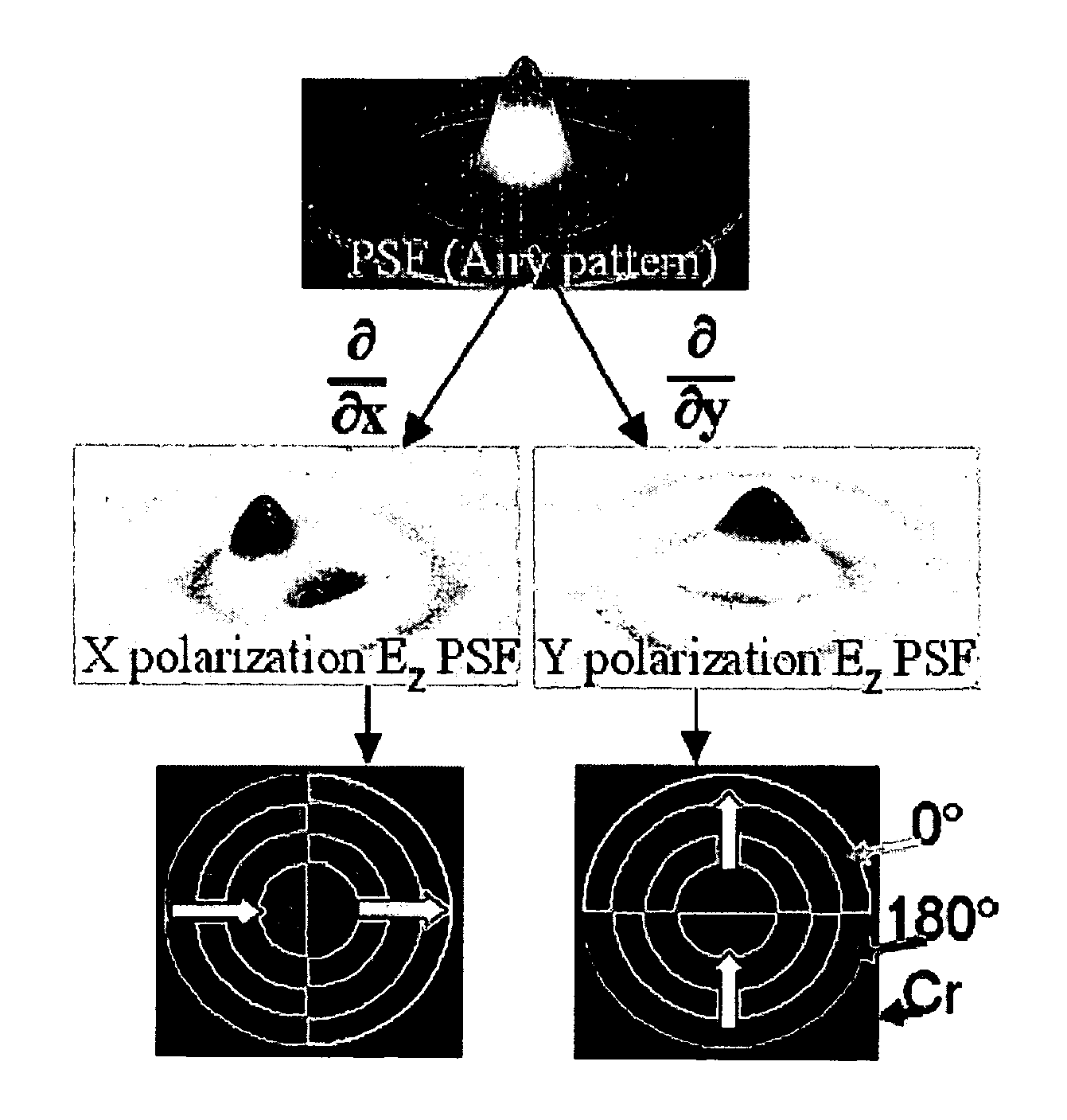
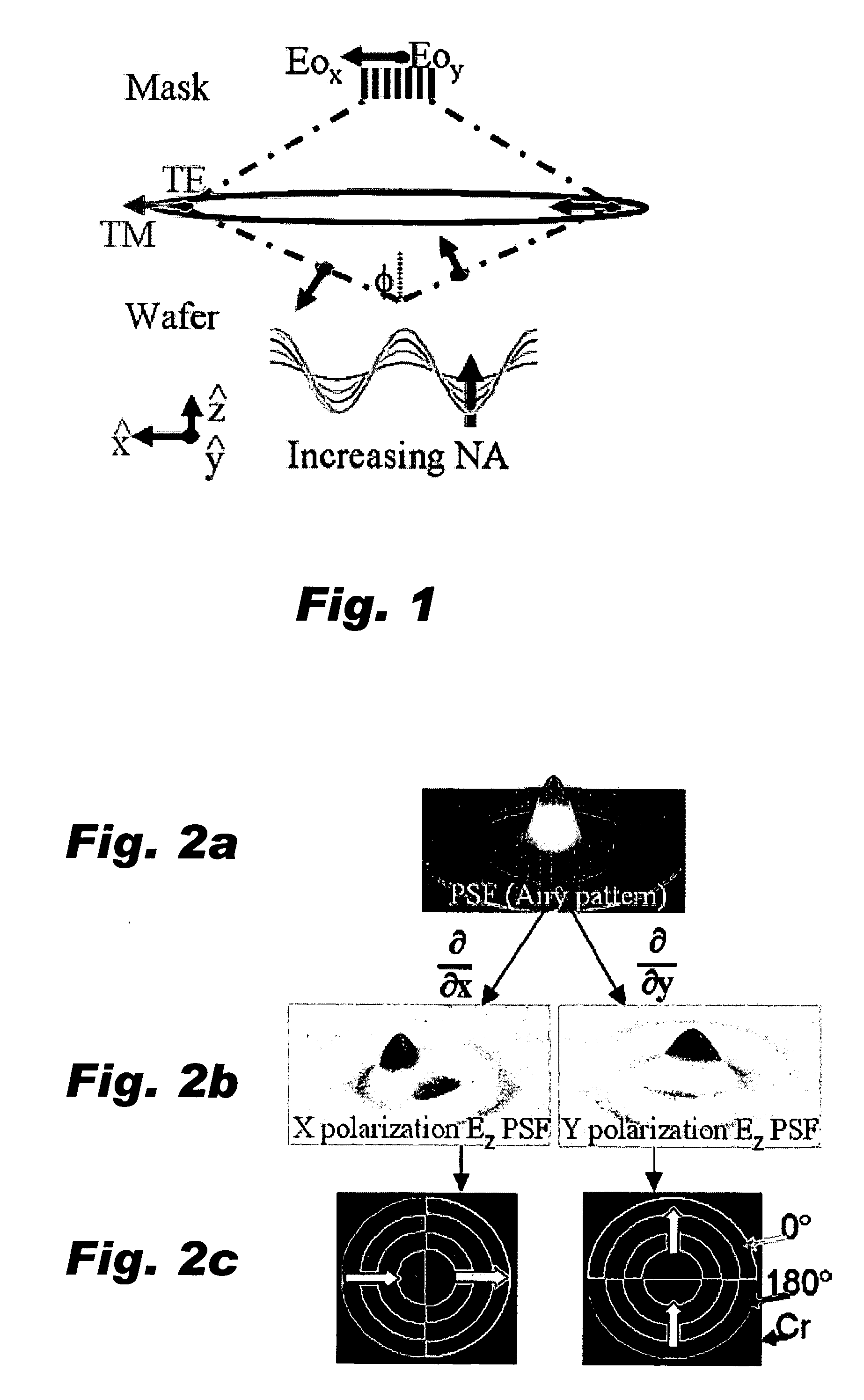
[0022] As noted above, high numerical aperture (NA) lens systems allow for large angle spatial frequencies which, in turn, produce smaller features on the wafer. However, a generally unwanted side effect of high NA imaging is the introduction of an electric field component oriented in the z direction, or normal to the wafer plane. This z component of the electric field is dependent only on the polarization component oriented radially in the pupil, often referred to as the transverse magnetic (TM) component. As shown in FIG. 1, this z component originates from the oblique angle of incidence and, since intensity is the square of the electric field, becomes appreciable at high NA. Thus, in the realm of high NA imaging, traditional scalar diffraction theory begins to breakdown and the true vector nature of light must be considered.

[0023] The PSM polarimeters in accordance with the invention create a measurable z-component signal by engineering which polarization component becomes subje...


PUM


Abstract

A method to monitor the state of polarization incident on the photomask in projection printing is presented. The method includes a series of phase-shifting mask patterns that take advantage of high NA effects to create a signal dependent on only one incident polarization component. The patterns exist in two embodiments: a Radial Phase Grating (RPG) and Proximity Effect Polarization Analyzers (PEPA). The PEPAs are derived from basic principles and are theoretically the most sensitive patterns to polarization. A polarimeter is then constructed of six patterns of either embodiment that, when properly calibrated, is sufficient to measure the Stokes parameters of the incident illumination. A test reticle design is proposed, consisting of multiple polarimeters with an array of pinholes on the backside of the photomask. This technique is able to monitor any arbitrary illumination scheme for a particular tool. Calibration of the test mask is required. However, proper calibration is likely to enable accurate full pupil polarization characterization, even when severe mask topography effects and reasonable maskmaking limitations are considered.

Description

CROSS REFERENCE TO RELATED APPLICATIONS [0001] This application claims priority from U.S. Provisional Application 60 / 654,346, filed Feb. 18, 2005, which is incorporated herein by reference for all purposes.BACKGROUND OF THE INVENTION [0002] This invention relates generally to image forming optical systems, and more particularly the invention relates to phase shifting test mask patterns for characterizing illumination and mask quality in such systems. [0003] A phase shifting mask alters the phase of light passing through certain areas of a photo mask in order to utilize destructive interference to improve resolution and depth of focus in optical lithography. The semiconductor industry is now considering such masks for use in fabricating integrated circuits such as mega bit memory and microprocessors which contain millions of transistors. [0004] The phase shifting mask and its use in an image forming optical system must be free of printable defects. To this end, a mask with phase shif...

Claims


Application Information

Patent Timeline
Patent Type & Authority Applications(United States)
IPC IPC(8): G01J4/00
CPCG01J4/04G03F7/70566G03F7/70591
Inventor MCINTYRE, GREGORY R.NEUREUTHER, ANDREW R.
Owner RGT UNIV OF CALIFORNIA
Why Eureka
Try Eureka