

Fuel cell system and method of shutting down the same
- Summary
- Abstract
- Description
- Claims
- Application Information
AI Technical Summary
Benefits of technology
Problems solved by technology
Method used
Image

Examples
first preferred embodiment
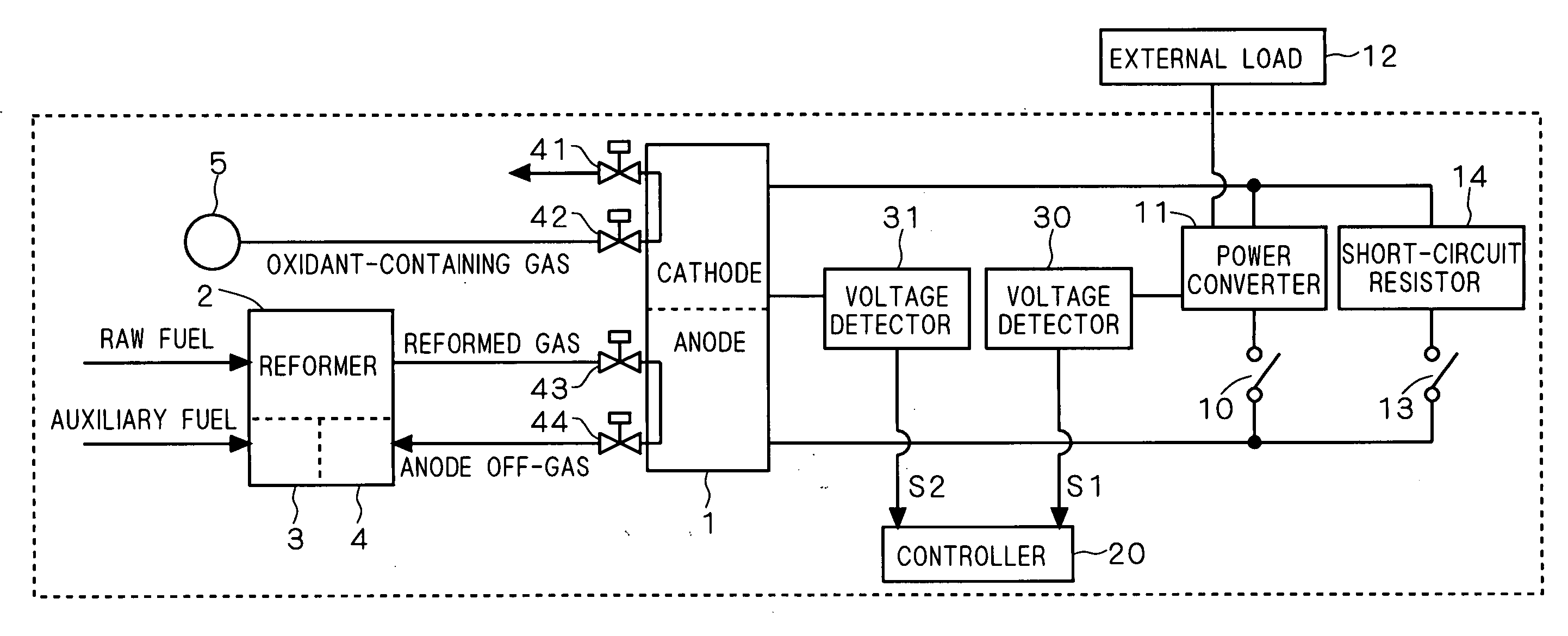
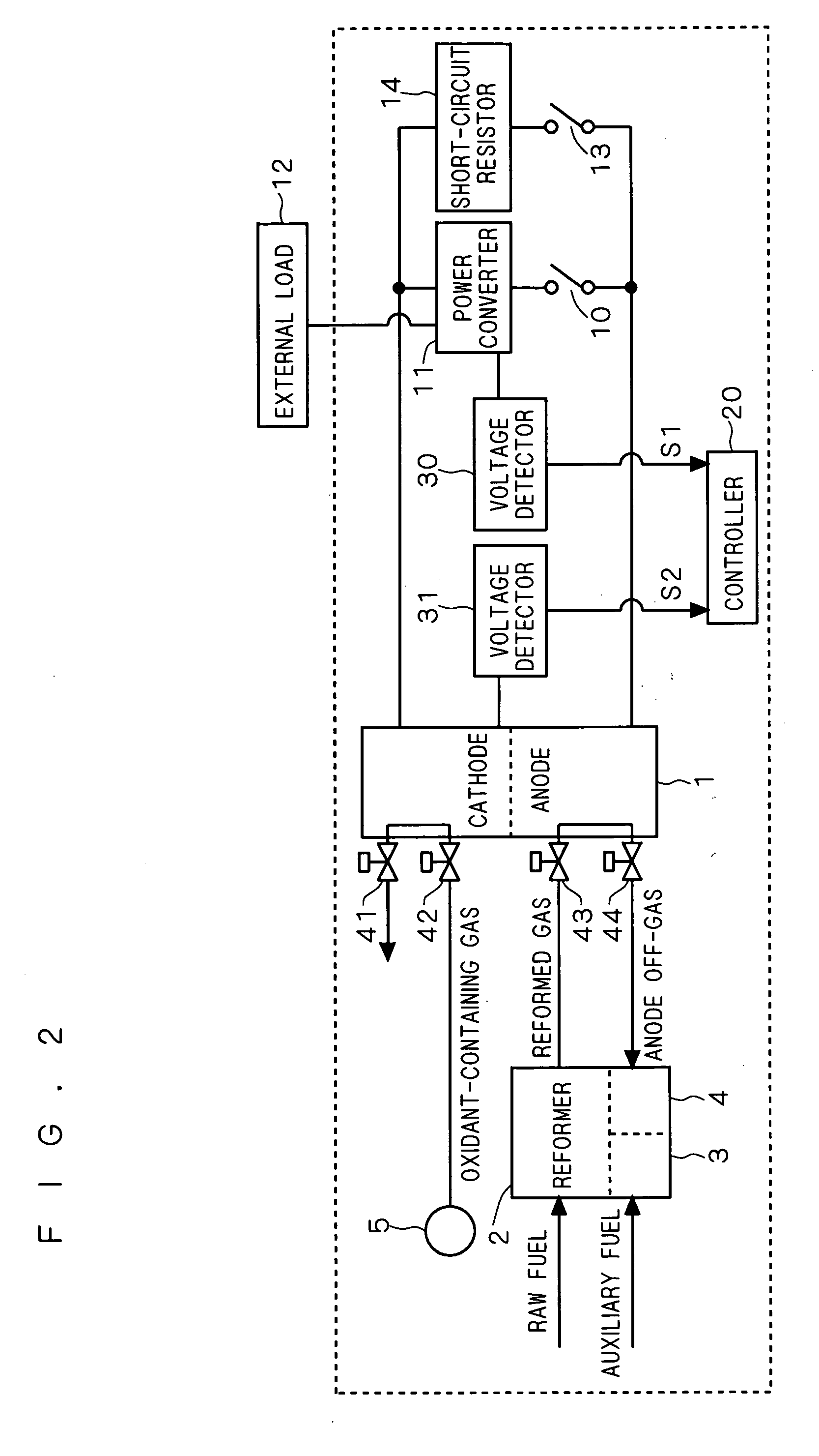
[0024]FIG. 2 is a block diagram systematically showing the configuration of a fuel cell system according to a first preferred embodiment of the present invention. In FIG. 2, the system generally includes a fuel cell stack (made up of a plurality of stacked cells) 1 having a cathode and an anode opposed to each other with an electrolyte (not shown) interposed therebetween, a reformer 2 for producing a hydrogen-containing gas (reformed gas) from a raw fuel and supplying the hydrogen-containing gas to the anode, and an oxidant-containing gas source 5. The oxidant-containing gas source 5 and its valves 42 and 41 constitute an “oxidant-containing gas supply path” along which an oxidant-containing gas such as air is supplied to the cathode.
[0025] The oxidant-containing gas and reformed gas are supplied to the fuel cell stack 1 through valves 42 and 43, respectively. The oxidant-containing gas undergone reaction on the cathode of the fuel cell stack 1 is discharged through the valve 41. T...
second preferred embodiment
[0035] In the first preferred embodiment, it is assumed that power cannot be consumed when the current value I reaches approximately zero in the power converter 11 shown in FIG. 2, that is, the operable lower limit voltage value of the power converter 11 is assumed to be not small.
[0036] However, if the power converter 11 is operable until the current value I reaches approximately zero (if the operable lower limit voltage value is relatively small), the whole power during the shutdown procedure may be consumed in the external load 12 through the power converter 11. In this case, when it is judged “YES” in step 102 shown in FIG. 3, that is, upon receipt of the signal S1, the controller 20 may immediately short the output of the fuel cell stack 1 in step 103 and stop the reformer 2 in step 104.
[0037] Therefore, according to the present embodiment, the capacitance of the short-circuit resistor 14 can be made still smaller than in the first preferred embodiment, or alternatively, the ...
third preferred embodiment
[0038] In the first preferred embodiment, the controller 20 determines the timing of switching to the short-circuit resistor 14 whether or not the signal SI is received in step 102 of the shutdown procedure shown in FIG. 3. Instead of this method, the controller 20 may determine the timing of switching to the short-circuit resistor 14 judging a drop in output voltage by comparing the value of the signal S2 output from the voltage detector 31 with a predetermined value (which is an experimentally predetermined value and corresponds to the above-mentioned threshold value in the first preferred embodiment). In this case, the voltage detector 30 becomes unnecessary.
[0039] More specifically, according to the present embodiment, the voltage detector 31 and controller 20 constitute the “current value control section”. Conversely saying, the current value control section includes the voltage detector 31 for detecting the output voltage of the fuel cell stack 1 and outputting the result of ...
PUM
 Abstract
Description
Claims
Application Information