
Clock recovery systems and methods for adjusting phase offset according to data frequency

a phase offset and clock recovery technology, applied in the field of clock recovery systems and methods, can solve problems such as errors during the receipt of data signals

Active Publication Date: 2006-08-24
SAMSUNG ELECTRONICS CO LTD
View PDF2 Cites 14 Cited by
  • Summary
  • Abstract
  • Description
  • Claims
  • Application Information

AI Technical Summary

Benefits of technology

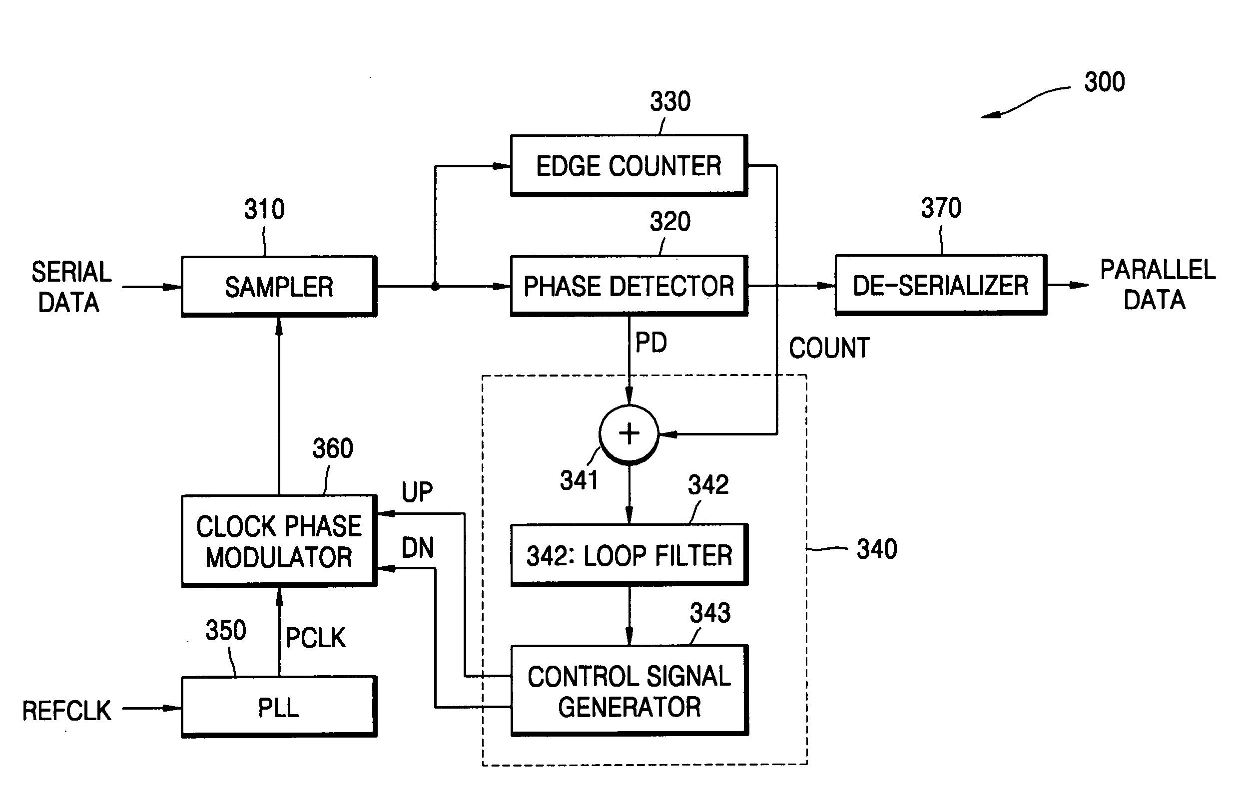
[0014] In still other embodiments of the present invention, the controller is further configured to generate the first and second control signals such that an amplitude of the first control signal is greater than an amplitude of the second control signal so as to move the phase of the modulated clock signal to the right of a center of an input data signal eye if the transition edge count indicates that the input data signal has a high frequency, and to generate the first and second control signals such that the amplitude of the second control signal is greater than the amplitude of the first control signal so as to move the phase of the modulated clock signal to the left of the center of the input data signal eye if the transition edge count indicates that the input data signal has a low frequency.
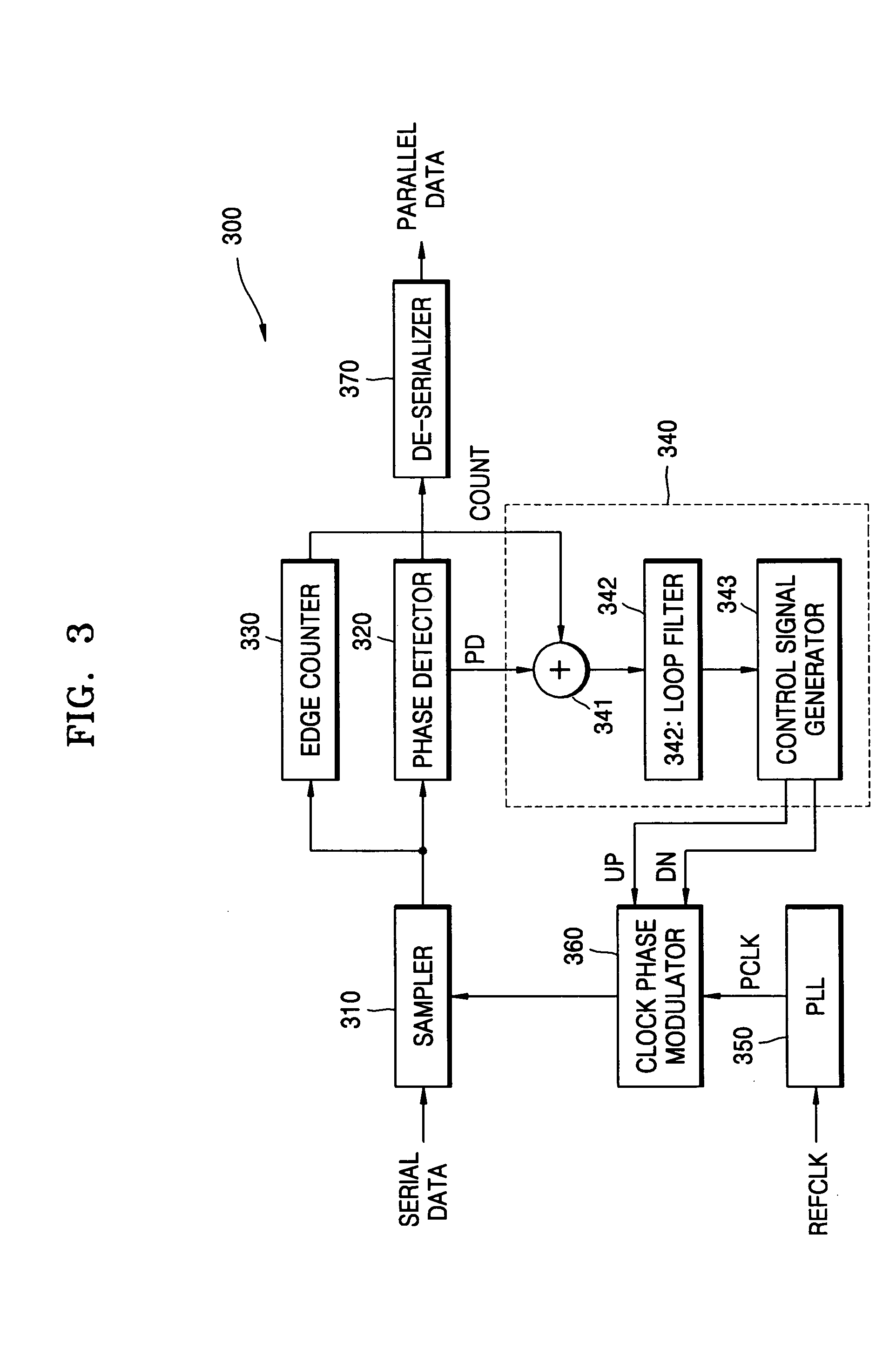
[0015] In still other embodiments of the present invention, the controller comprises a mixer that is configured to generate an output responsive to the comparison result and the transition edge count, a loop filter that is configured to generate an average of the mixer output, and a control signal generator that is configured to compare the average with a threshold to generate the first and second control signals.
[0016] In still other embodiments, the control signal generator is further configured to generate the first and second control signals, such that the amplitude of the first control signal is greater than the amplitude of the second control signal when the average is greater than the threshold and the amplitude of the first control signal is less than the amplitude of the second control signal when the average is less than the threshold.
[0017] In still other embodiments, the controller comprises a loop filter that is configured to generate an average of the comparison result, a mixer that is configured to generate an output responsive to the average and the transition edge count, and a control signal generator that is configured to compare the mixer output with a threshold to generate the first and second control signals.
[0018] In still other embodiments, the control signal generator is further configured to generate the first and second control signals, such that the amplitude of the first control signal is greater than the amplitude of the second control signal when the mixer output is greater than the threshold and the amplitude of the first control signal is less than the amplitude of the second control signal when the mixer output is less than the threshold.
[0019] In further embodiments of the present invention, a clock recovery method includes sampling an input data signal in synchronization with a modulated clock signal to generate a sample of the input data signal, computing a position of a transition edge of the input data signal using the sample data signal, comparing the computed position with a position of an edge of the modulated clock signal to generate a comparison result, counting transition edges of the sample data signal, generating first and second control signals based on the comparison result and the count of the transition edges, and generating the modulated clock signal by adjusting a phase of an input clock signal responsive to the first and second control signals, such that the phase is increased in response to the first control signal and reduced in response to the second control signal.

Problems solved by technology

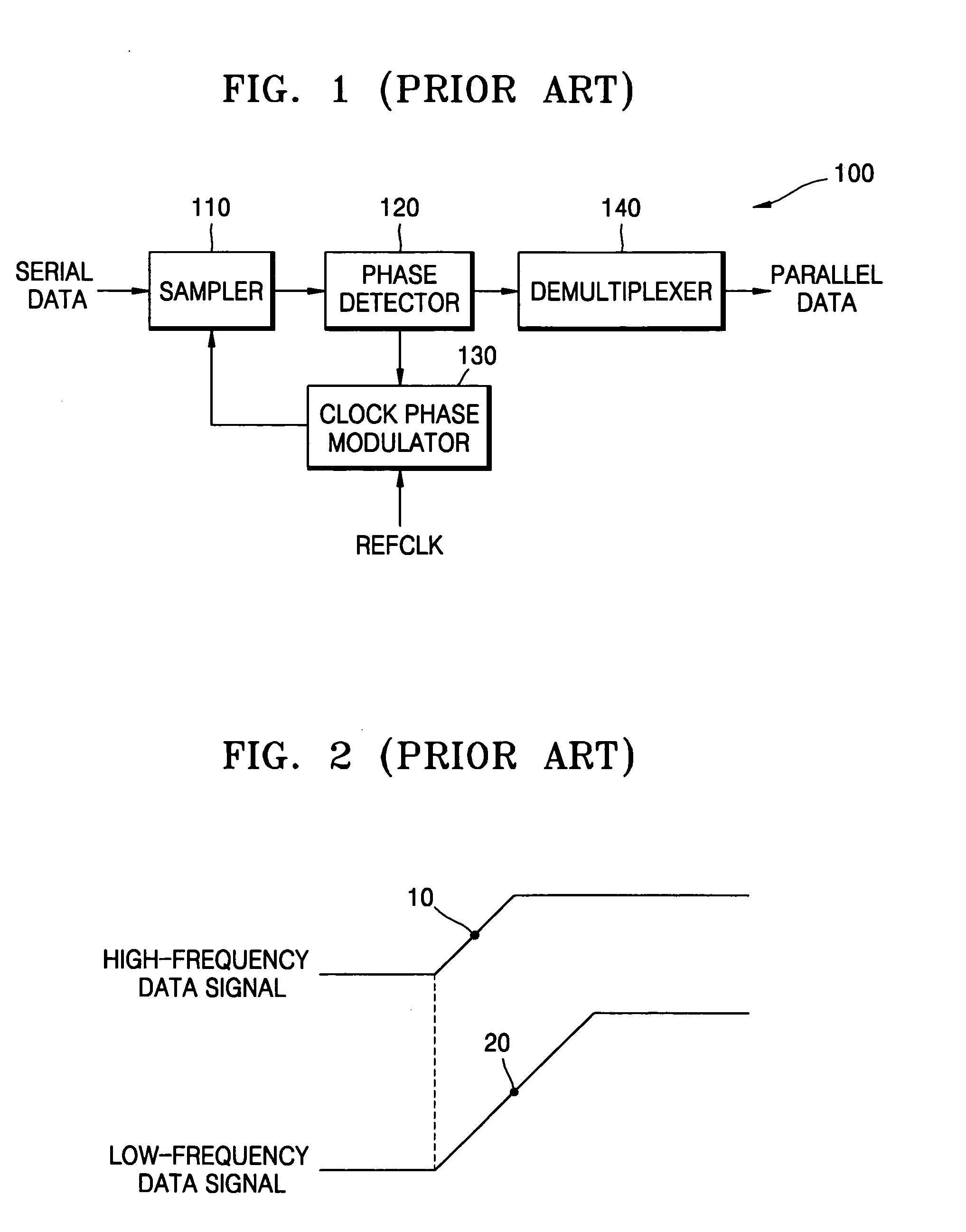
However, if a received data signal contains an Inter Symbol Interference (ISI) jitter due to transmission loss characteristics of a transmission line, amplitudes of a high-frequency data signal and a low-frequency data signal are different from each other and, thus, the centers of the transitions are not the same even when transitions in the high-frequency and low-frequency data signals begin at the same position.
In this case, because a timing margin of a data signal whose frequency is changed may be insufficient, an error may occur during the receipt of a data signal.

Method used


Image

  • Clock recovery systems and methods for adjusting phase offset according to data frequency
  • Clock recovery systems and methods for adjusting phase offset according to data frequency
  • Clock recovery systems and methods for adjusting phase offset according to data frequency

Examples


Embodiment Construction

[0028] While the invention is susceptible to various modifications and alternative forms, specific embodiments thereof are shown by way of example in the drawings and will herein be described in detail. It should be understood, however, that there is no intent to limit the invention to the particular forms disclosed, but on the contrary, the invention is to cover all modifications, equivalents, and alternatives falling within the spirit and scope of the invention as defined by the claims. Like reference numbers signify like elements throughout the description of the figures.

[0029] As used herein, the singular forms “a,”“an,” and “the” are intended to include the plural forms as well, unless expressly stated otherwise. It will be further understood that the terms “includes,”“comprises,”“including,” and / or “comprising,” when used in this specification, specify the presence of stated features, integers, steps, operations, elements, and / or components, but do not preclude the presence o...


PUM


Abstract

A clock recovery system includes a sampler that is configured to sample an input data signal in synchronization with a modulated clock signal to generate a sample of the input data signal. A phase comparator is configured to compute a position of a transition edge of the input data signal using the sample data signal, and to compare the computed position with a position of an edge of the modulated clock signal to generate a comparison result. An edge counter is configured to count transition edges of the sample data signal. A controller is configured to generate first and second control signals based on the comparison result and the count of the transition edges. A clock phase modulator is configured to generate the modulated clock signal by adjusting a phase of an input clock signal responsive to the first and second control signals, such that the phase is increased in response to the first control signal and reduced in response to the second control signal.

Description

CROSS-REFERENCE TO RELATED PATENT APPLICATION [0001] This application claims the priority of Korean Patent Application No. 10-2005-0011440, filed on Feb. 7, 2005, in the Korean Intellectual Property Office, the disclosure of which is hereby incorporated herein by reference in its entirety. BACKGROUND OF THE INVENTION [0002] 1. Field of the Invention [0003] The present invention relates to clock recovery systems and methods, and, more particularly, to clock recovery systems and methods for improving jitter tolerance. [0004] 2. Description of the Related Art [0005]FIG. 1 is a block diagram of a conventional clock recovery system 100. The conventional clock recovery system 100 includes a sampler 110, a phase detector 120, a clock phase modulator 130, and a demultiplexer 140. [0006] The sampler 110 obtains a sample data signal of a serial data input signal. The phase detector 120 detects the phase of the serial data input signal from the sample data signal. The clock phase modulator 130...

Claims


Application Information

Patent Timeline
Patent Type & Authority Applications(United States)
IPC IPC(8): G06F1/24G06F11/00
CPCH03L7/07H03L7/08H04L7/0331H03L7/00
Inventor OKAMURA, HITOSHI
Owner SAMSUNG ELECTRONICS CO LTD
Learn More